My wiring diagrams require that I use Hall Effect Sensors to measure the current being generated by either the main or backup alternator. This VansAirForce thread describes how an inexpensive AMPLOC KEY100 hall sensor can be used. It also details the connector and pins that can used. What is missing is a way to install the senor which is essentially just a large ring.
I have created a mounting shell for the sensor in anticipation of installation in the next few months. This design has not been used in an actual installation but I expect it will work as advertised.
The pixs below show the 3D printed shell I created so I can easily mount the sensor on the firewall while ensuring the connections are secure.
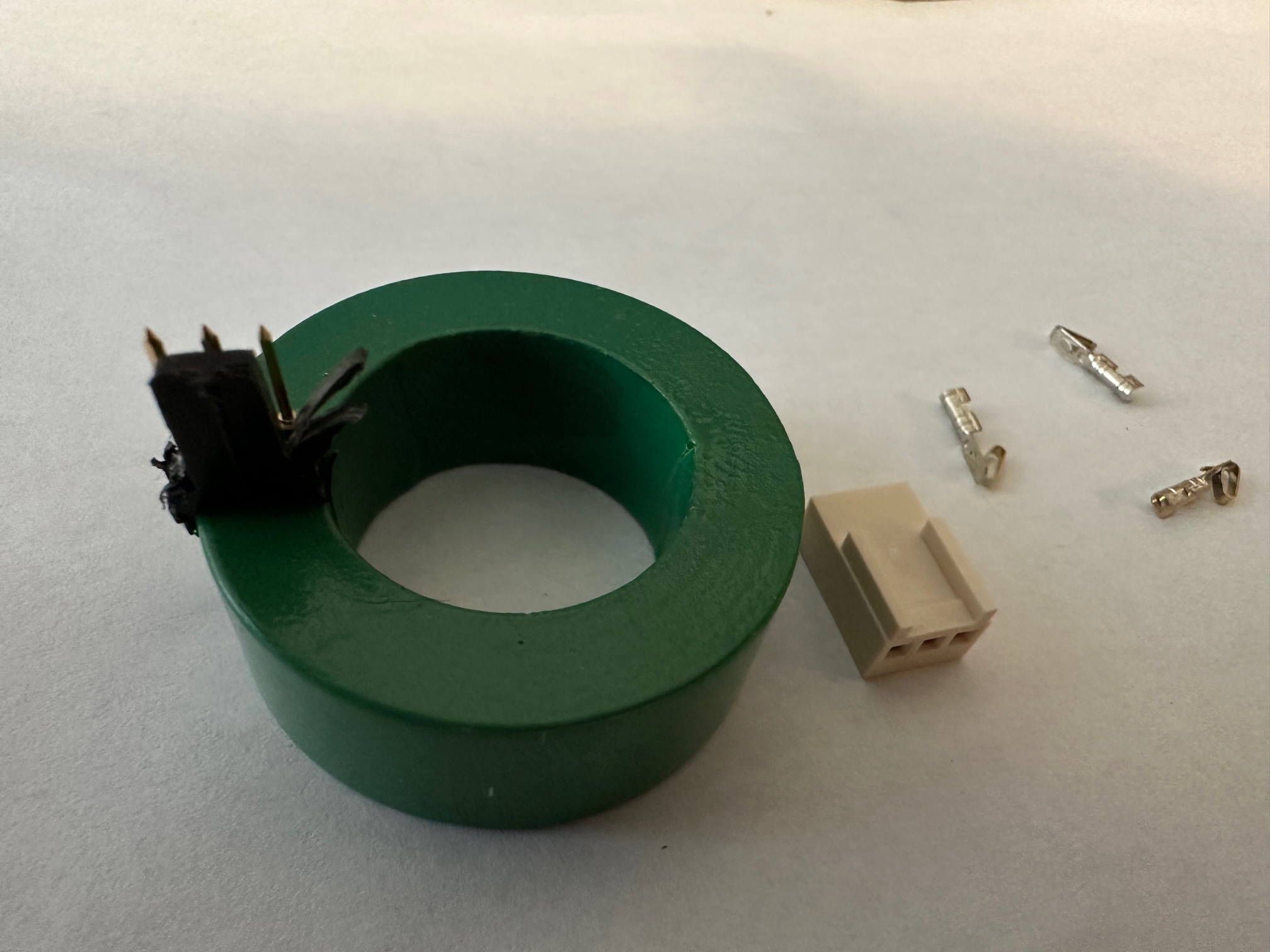
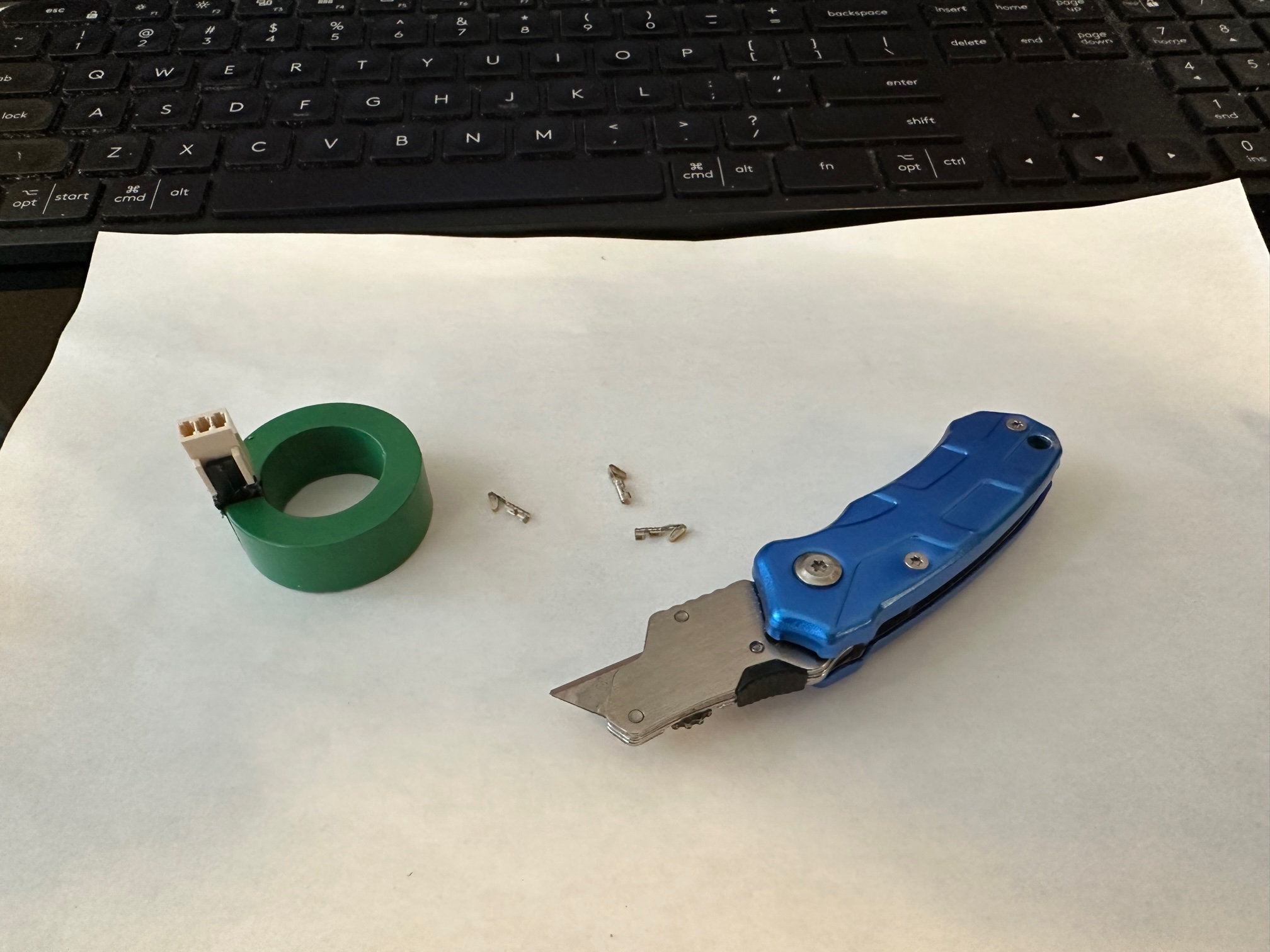
The pix on the left shows the green hall sensor. If you look closely, you will see that I have started shaving the black backer in front of the pins so the Molex connector can slide into place. Only the inside edge needs to be trimmed. The next pix shows the connector on the pins. You can also trim the “bars” on the Molex connector but I prefer to leave these in pace for support.
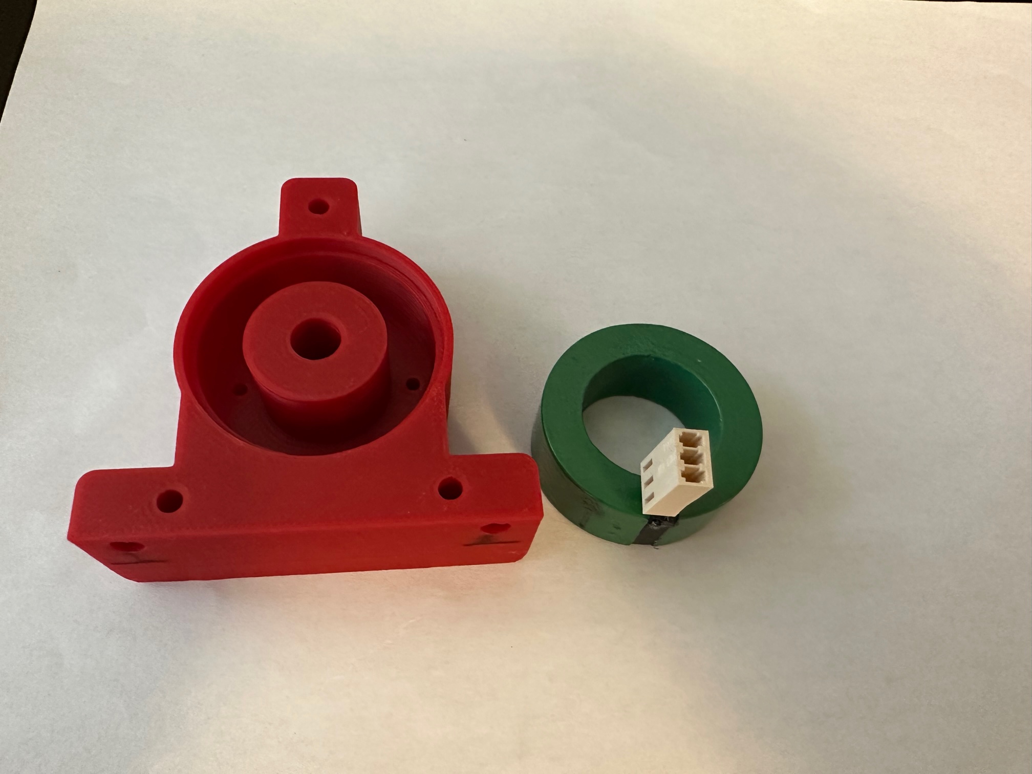
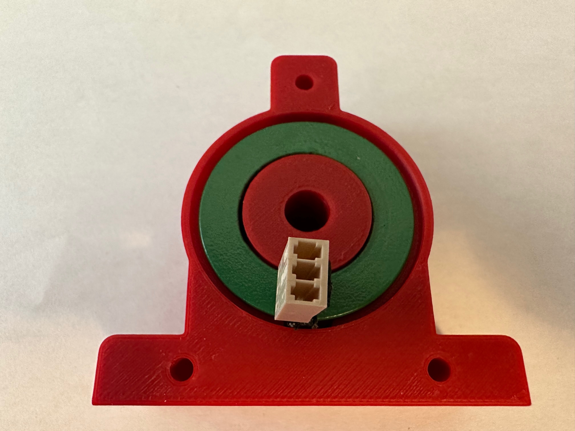
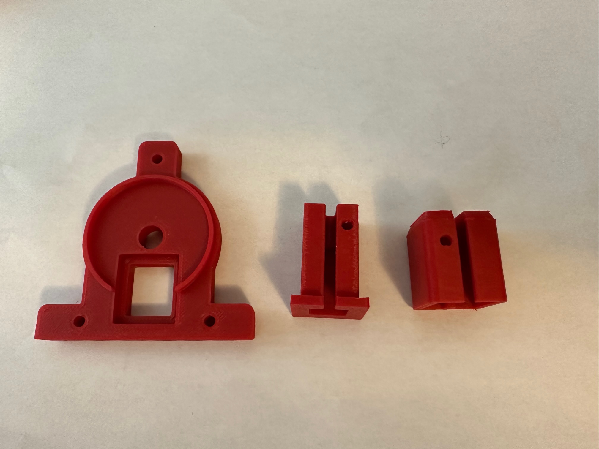
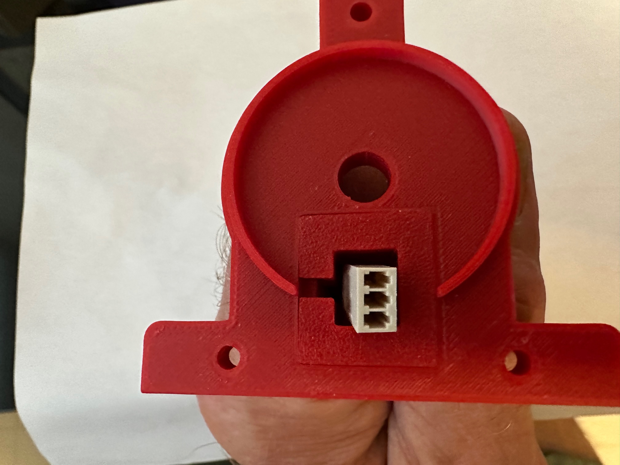
The first pix shows the mounting shell for the sensor. It is, by design, a snug fit. There are holes in the back that you can use to push the sensor out of the shell if necessary. The middle pix shows the sensor installed along with the Molex connector. I have not installed the wires / pins in the connector. The last pix shows the cover plate components.
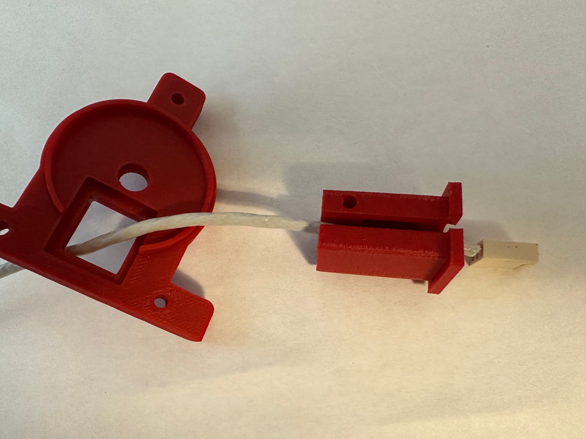
To assemble the components, feed the sensor wire and connector through the cover plate and into the center insert – Pix 1. Then press the center insert into the cover plate. It should be flush on the inside – pix 2. Next slide cover plate onto the shell with the Hall sensor with the connector on the sensor pins. As you assemble, gently pull the wire so that everything fits. You want the Molex connector to remain on the pins – take care that they do not come off as you pull the wire. – GO SLOW. Lastly slide the cover sleeve over the center insert. When it is in place, the sensor wire is held securely – it will not easily pull out. The hole in the sleeve will allow you to install a #4 screw / cotter pin / safety wire to keep the sleeve from moving.
`
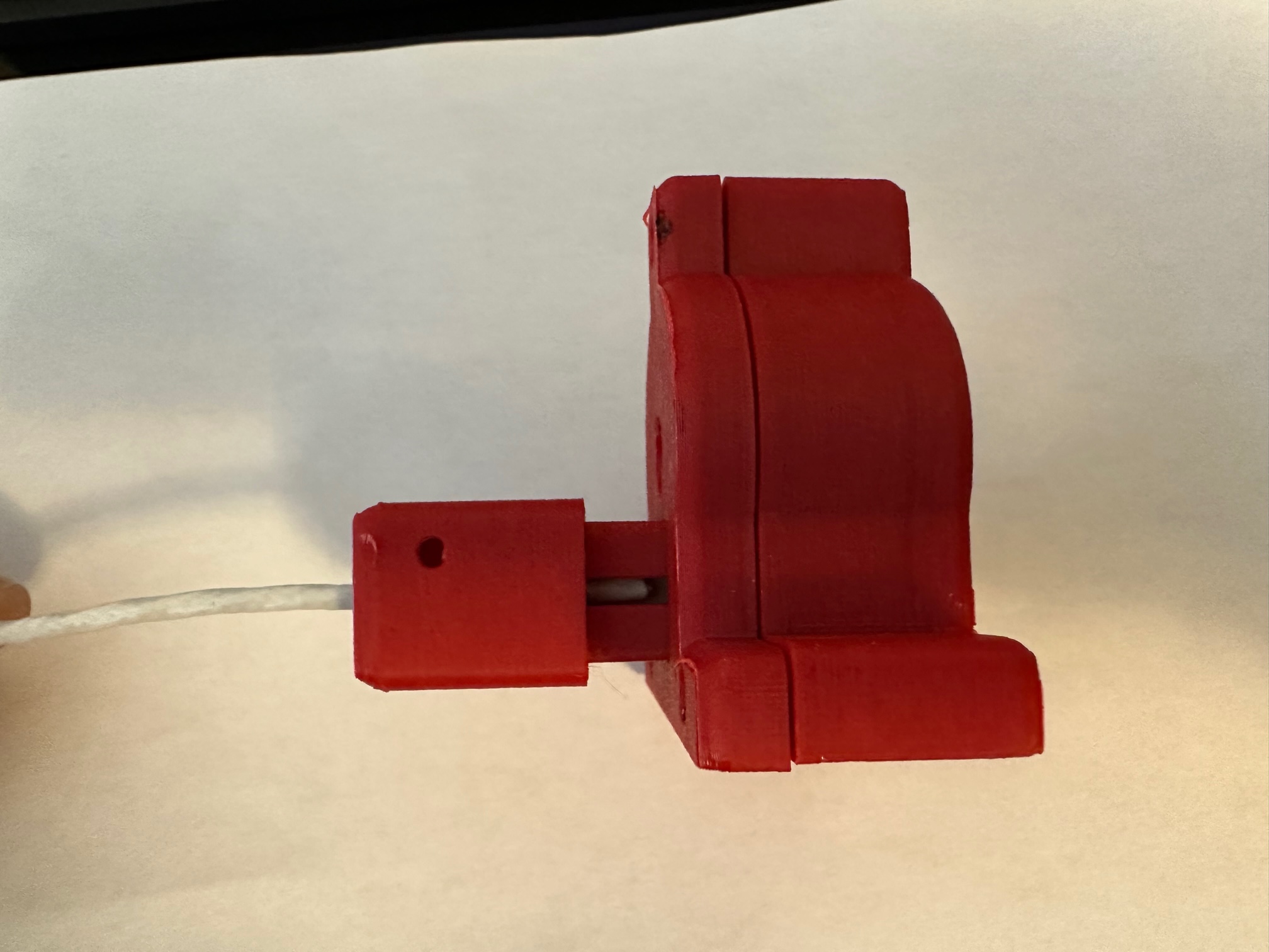
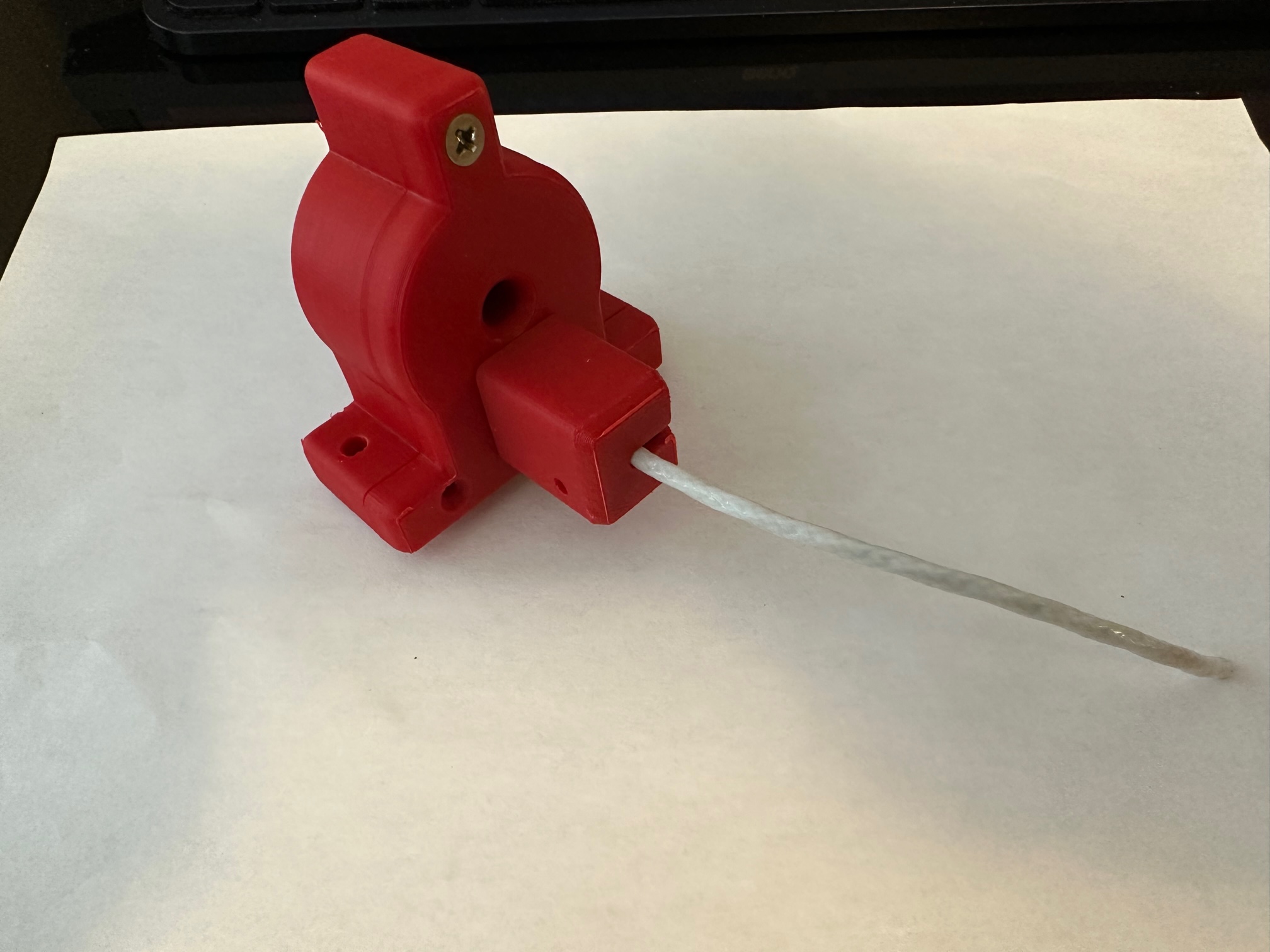
Here is what the assembled housing will look like. I have shown only one of three flush #4 (3/4″) screws that hold the case together. There are are #4 nylocs on the rear. You can also see the mounting screw holes (#8) on the base.
After I took the above, I realized that the hole needed to be larger to allow the alternator wire AND connector needed to go through the hole. The 3D printer files have the larger hole.
Once I install my sensors in the coming months, I will update with actual install pix. For now here are the STL files.