The avionics install on this build has been much easier on this build versus my previous two projects. There were two things that I have done that made things easier – first I have not installed the forward fuse skin nor have I installed the forward fuse ribs & panels. This means I have great access to the panel & sub panel.
It is important not to be complacent with all this great access. When installing boxes / wires / general stuff in the panel and importantly behind the subpanel, consider how you will access things later if there is a problem.
The pix below will give you a sense as to how I approached the install – unfortunately I didn’t take nearly as many pix as I should have.
Wiring secured 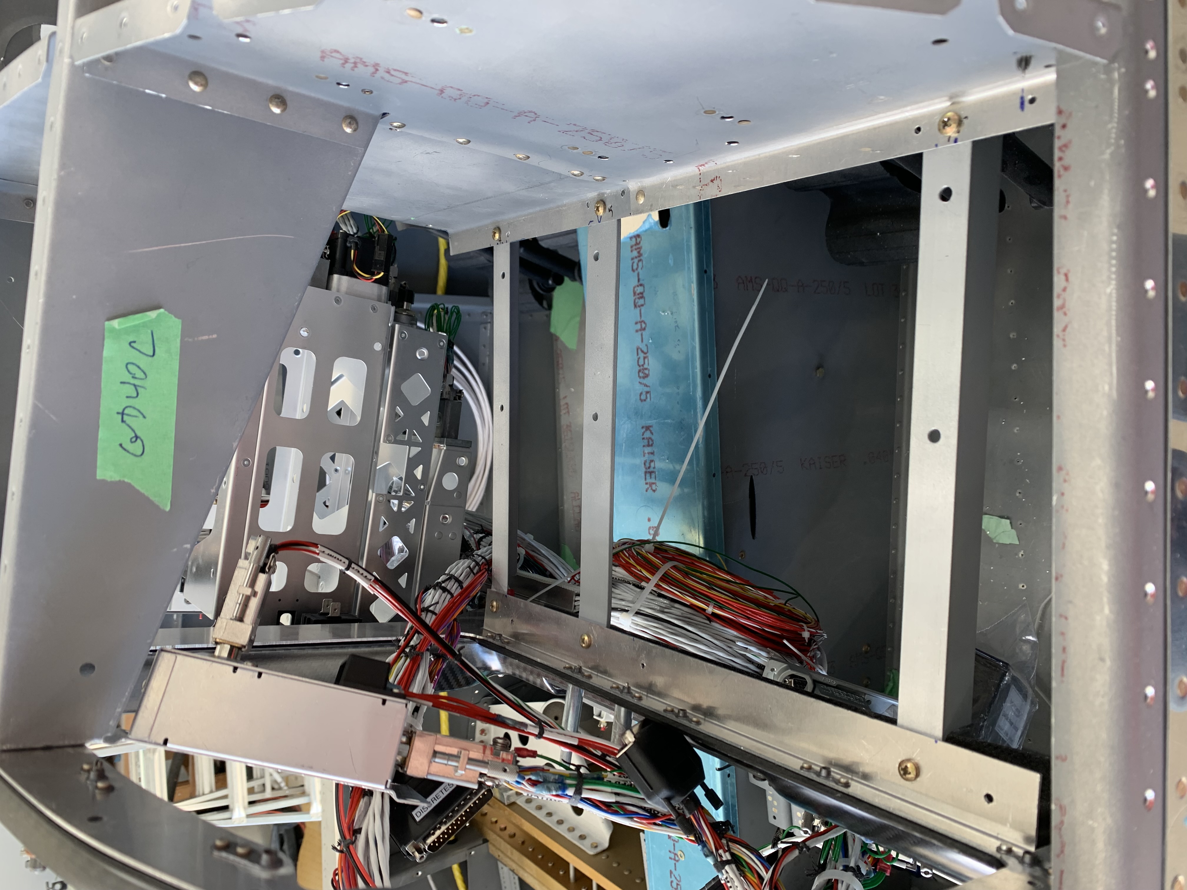
Supporting braces fabricated 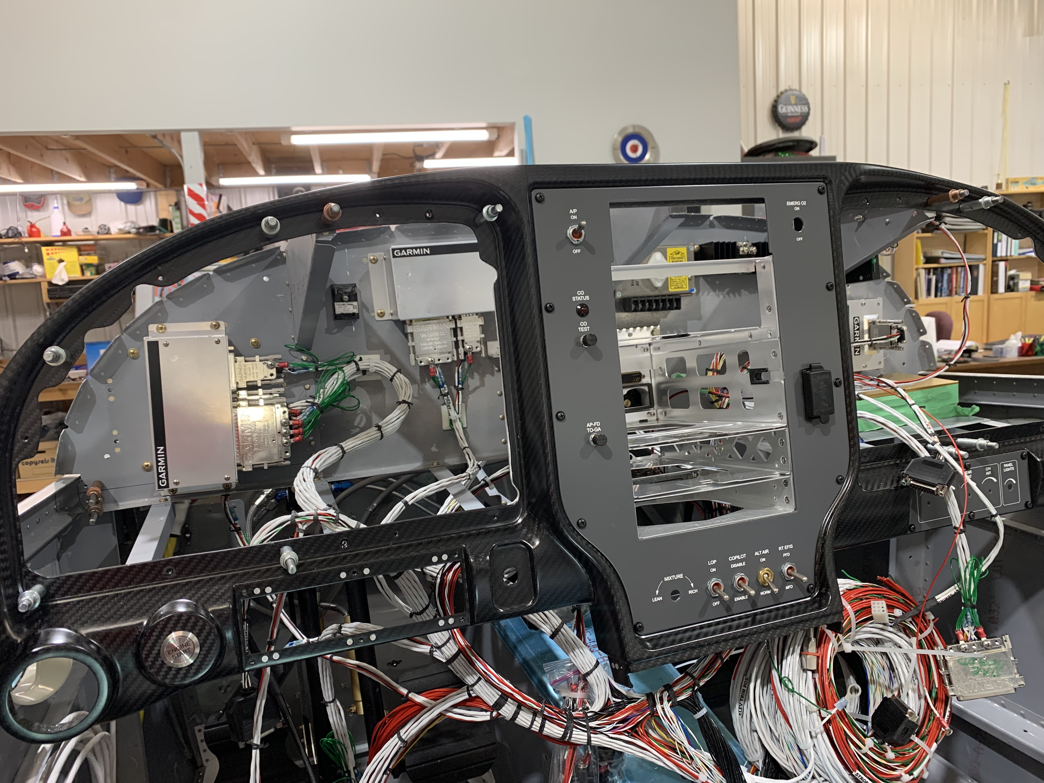
Panel slipped into place
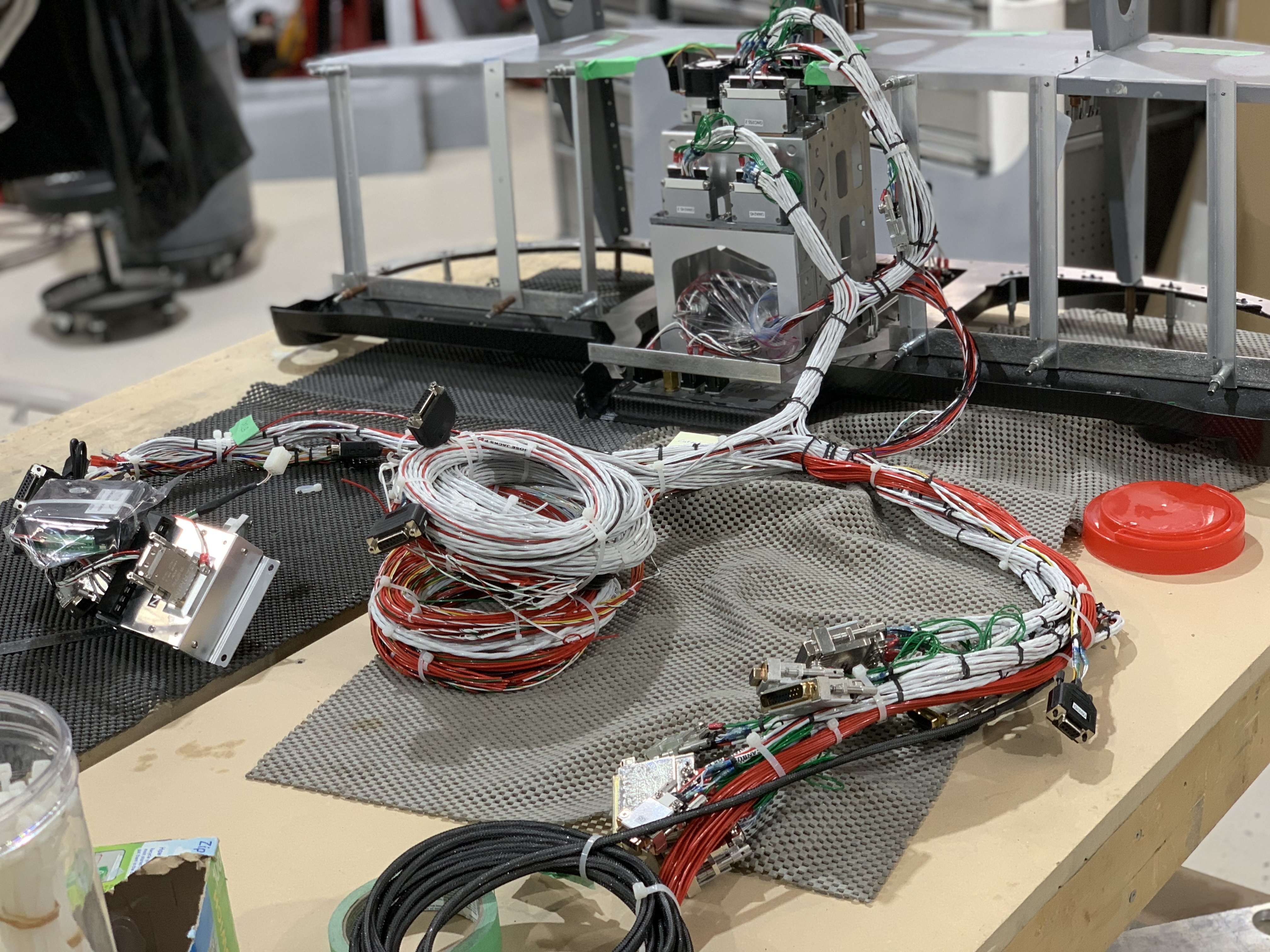
First I zip tied all the loose harness together. In my harness, some connectors went left, others right and a few were left in the center. I used el cheapo zip ties to gather these up so I wasn’t dealing with a bunch of loose connectors -that would come later.
In the first pix you will see some braces that run between the subpanel and the main panel bezel. What I did was clecoe’d the upper fuse assembly in place in the in the fuse and then attached the panel bezel. I then fabricated the braces that ran between the subpanel and the bezel (see second pix). As there is a bit of an angle on the sub panel, the connections were bent to account for the angle.
Next I spotted (roughly) where all the boxes were to go. I decided to mount all the boxes on the subpanel and leave the trays between the panel and subpanel for fuse blocks and the SDS ECU. The tray is not shown in pix 2 but you can see 4 attach holes on the two braces. I also installed nutplates on the sub panel for all the mounting bolts / screws required by the boxes being installed.
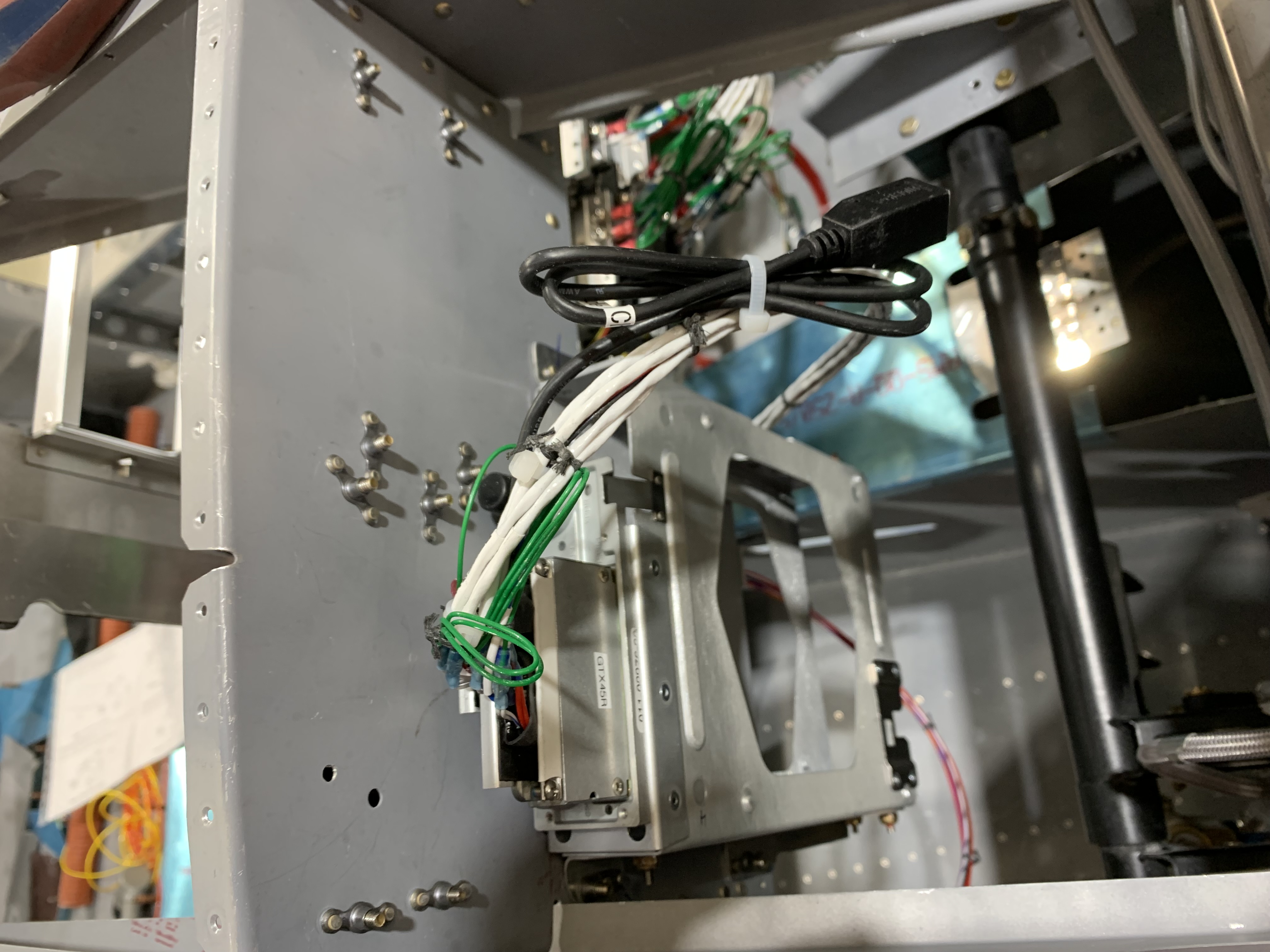
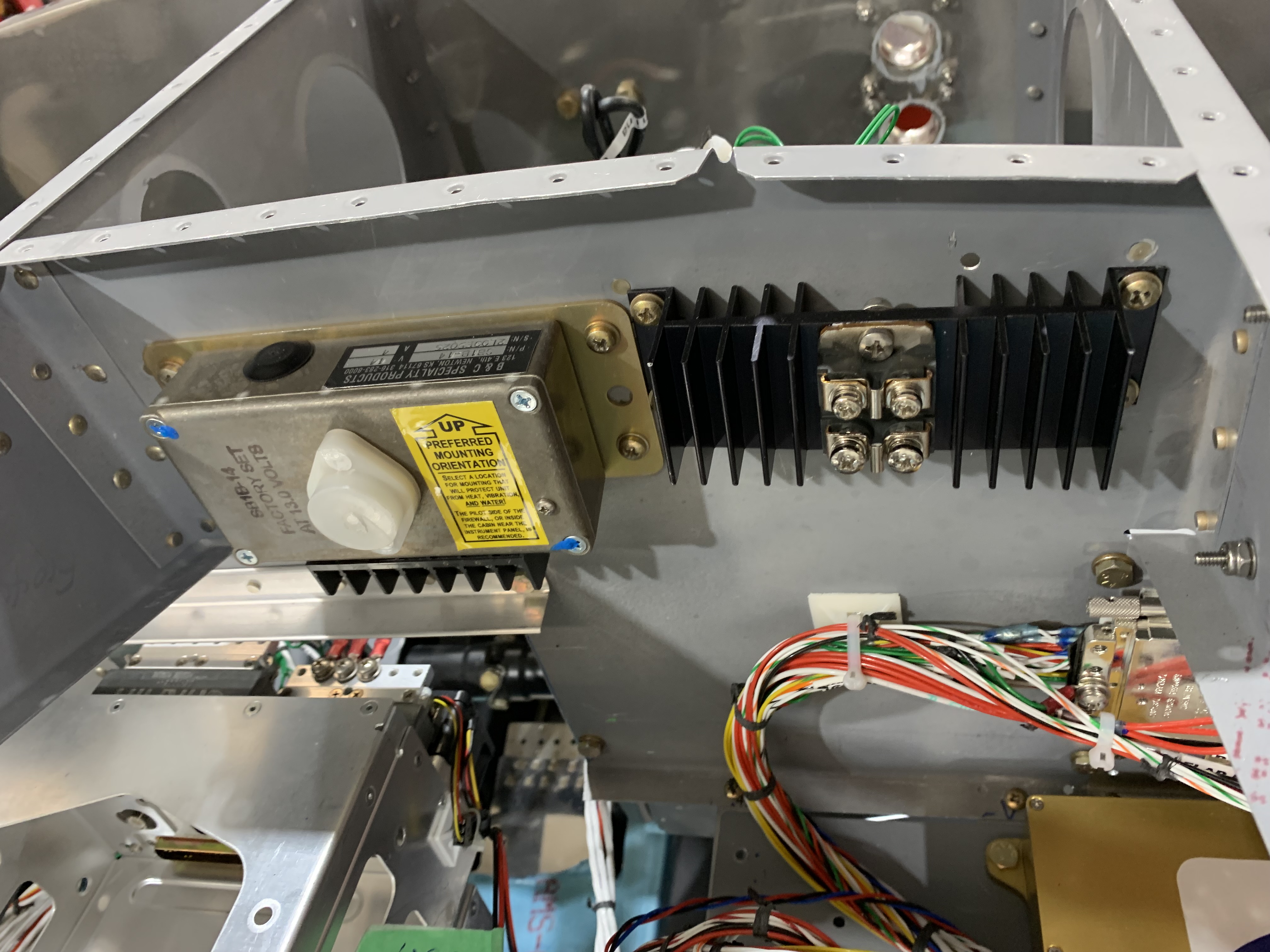
Finally, as shown in pix 3, I started installing the boxes attaching the connectors. The following pix give an idea of how things went.
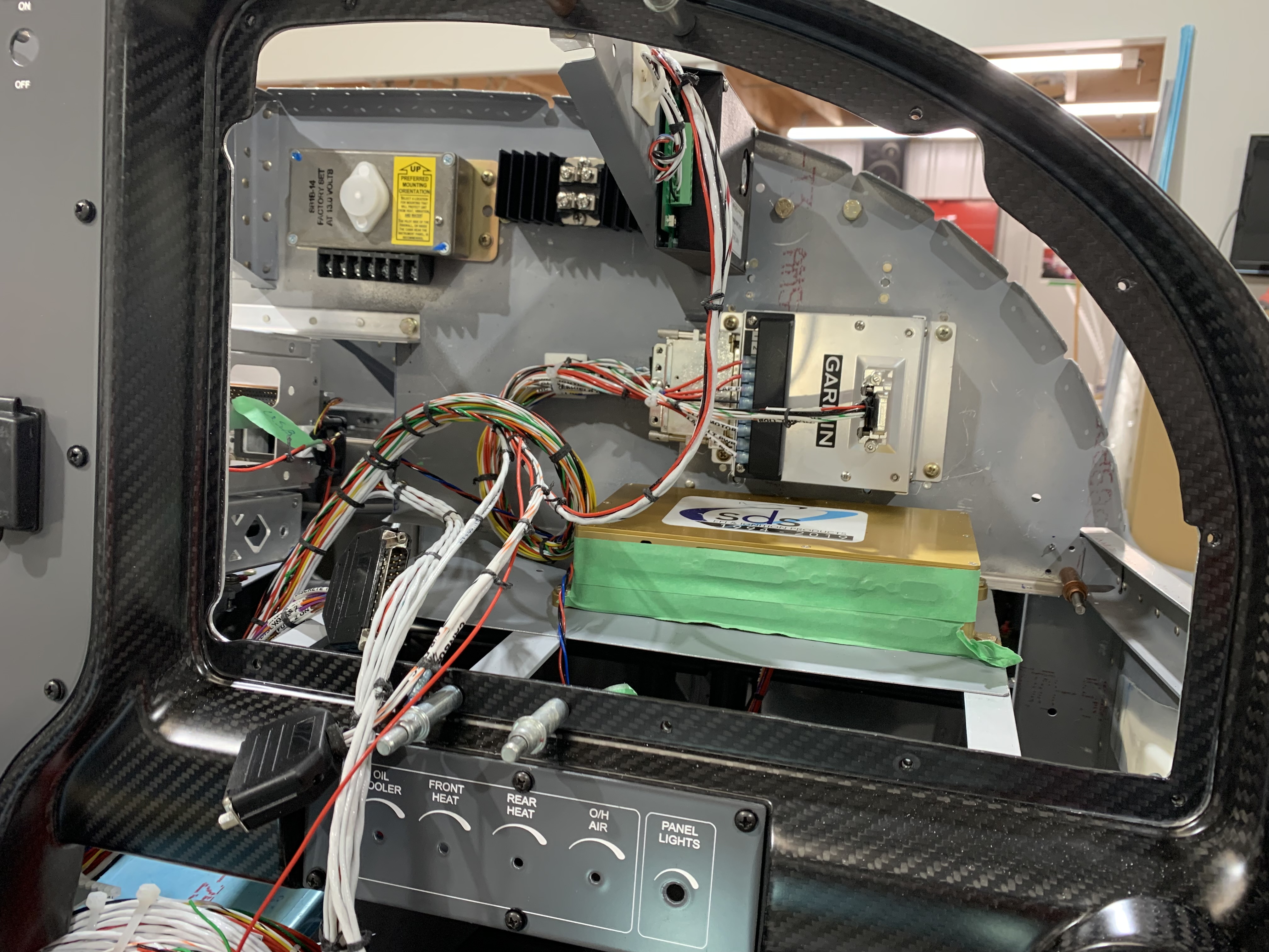
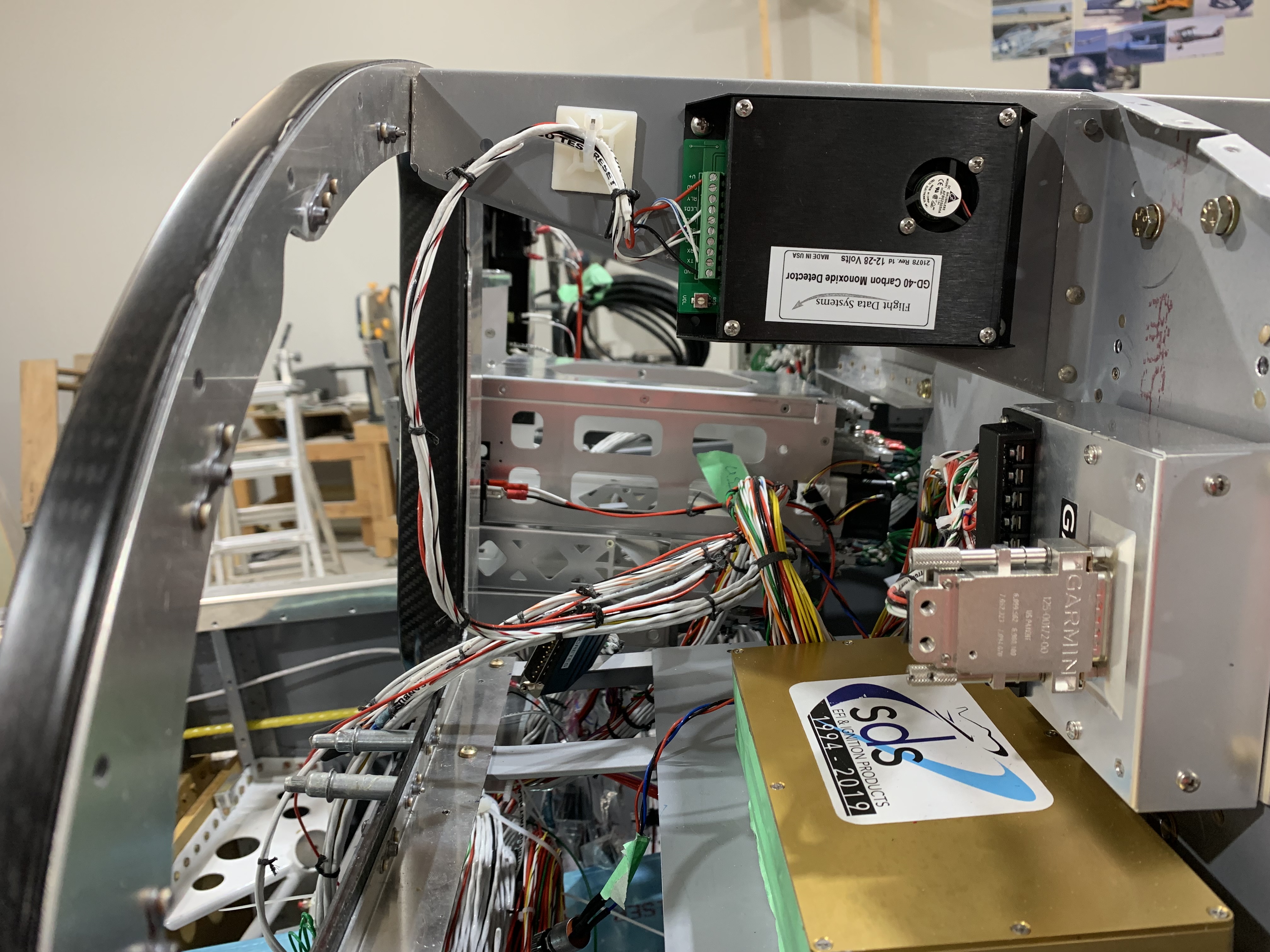
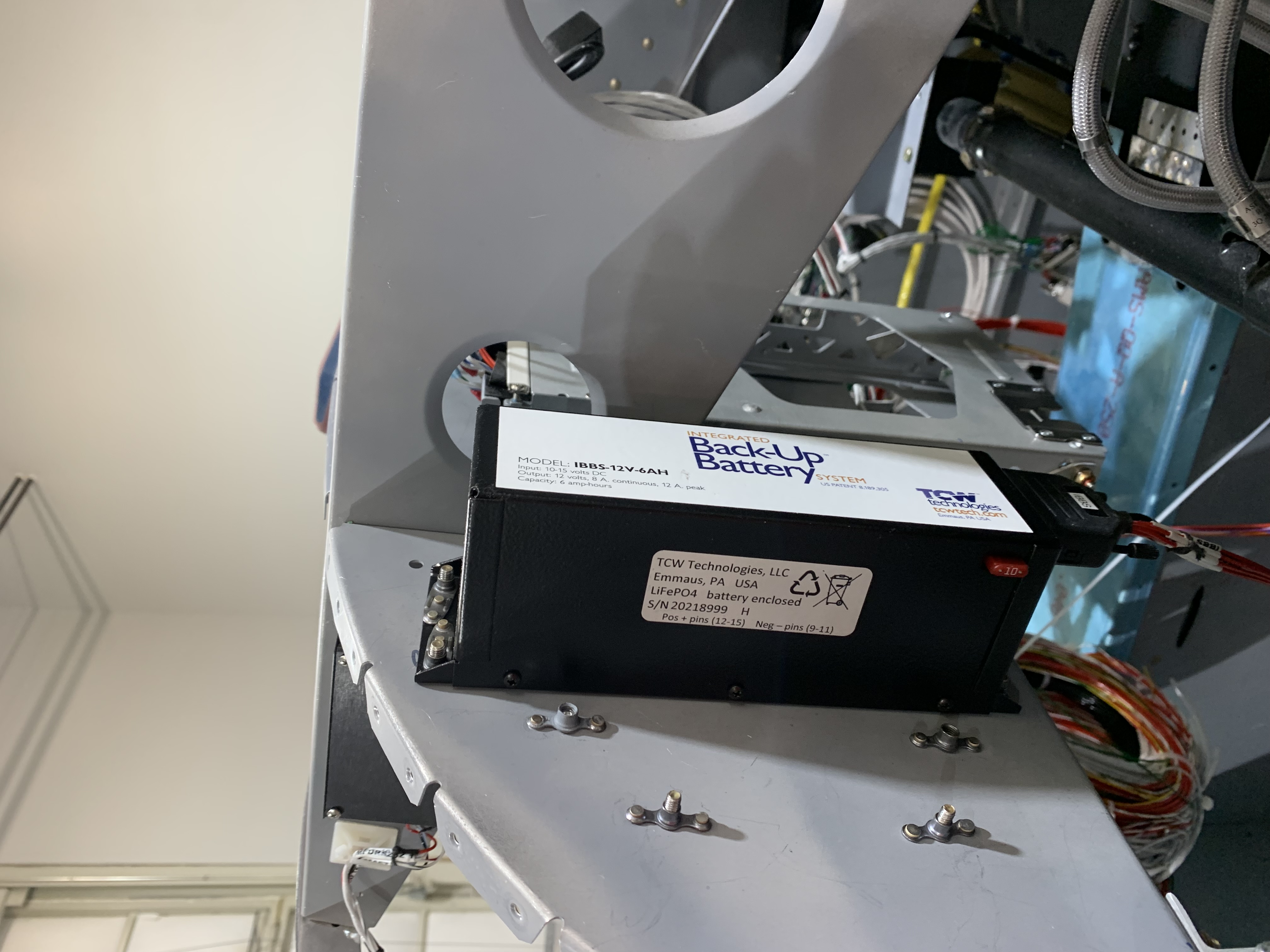
The first pix shows the how I used the front of the sub panel to great advantage. All of the boxes are accessible simply by removing the G3X MFD from the panel. I also used the rear of the subpanel as much as possible (provided I could get easy access the the boxes installed there). Pix 3 shows the TCW IBBS battery mounted behind the sub panel. However, by removing 4 bolts from the front, the box drops down. I did this buy installing nutplates on the IBBS box flanges.
This first pix below shows the GTX 345 transponder tray. In this case the transponder inserts from the bottom. If necessary, the full tray can be removed by removing 4 bolts that hold the mounting flanges to the subpanel. These are hard to see in the pix but if you look carefully you will see the ones on the left side of the tray.