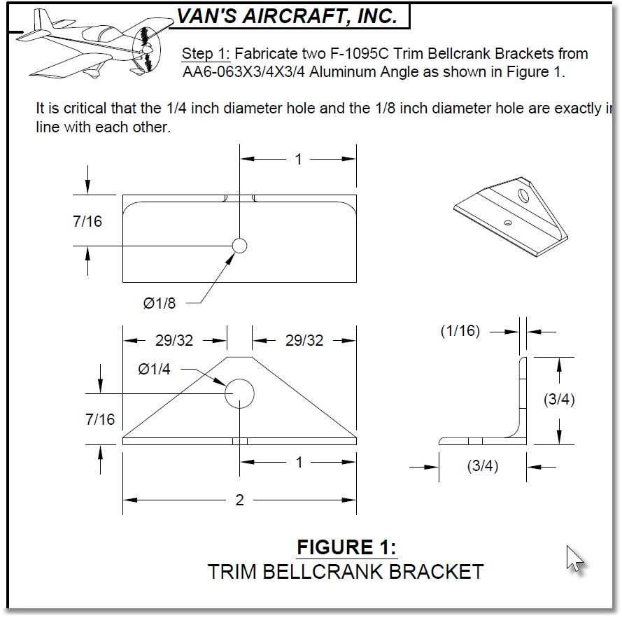
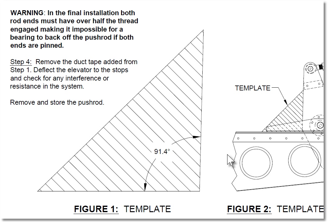
There are re a couple of brackets used on the elevator trim bellcrank where hole alignment is key. There is also a “wedge” that needs to be precisely created used in aligning the elevator bellcrank in the tail cone.
The plans requirements are shown below

I have created a couple of templates for the brackets. They nest inside the aluminum stock and allow the dimensions to be traced. The holes in the templates are 3/16 so the “F” drill bushing in the fuselage kit can be used to drill 1/8″ pilot holes. The template material is too soft to keep a drill bit from enlarging the hole. The 1/8″ pilot holes can be enlarged as required by the plans.
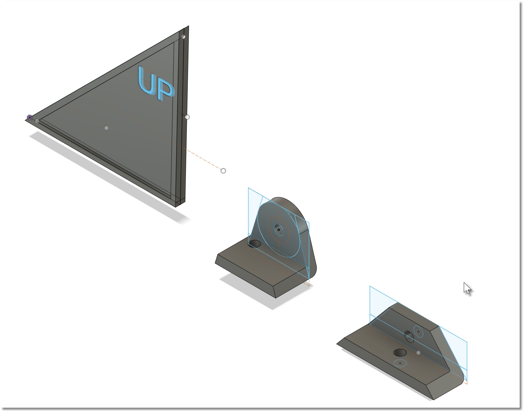
Here are pix from my CAD software of the above. I printed these in black so the 3D pix are easier to see than the actual brackets.
You can find the 3D Printer files here.