The starting point for the SDS installation is typically the fuel system. Fuel lines & fuel selector valve are installed when the fuselage is constructed. Although some builders put fuel filters in the tunnel, my preference is to only put fuel pumps in the tunnel and install filters in more accessible areas such as wing roots and/or the firewall.
Key Concepts
A key difference between the standard RV10 fuel system and the SDS system is that you will need to plumb a return fuel line to each fuel tank. The electric fuel pump(s) will move 2-3 times as much fuel to the engine than is required. The unused fuel is returned to the originating fuel tank.
Fuel pressure is regulated by a Borla fuel pressure regulator located FWF.
Typically, there are three fuel filters installed. One in each wing root and a third on the firewall.
Return Line To Fuel Tank
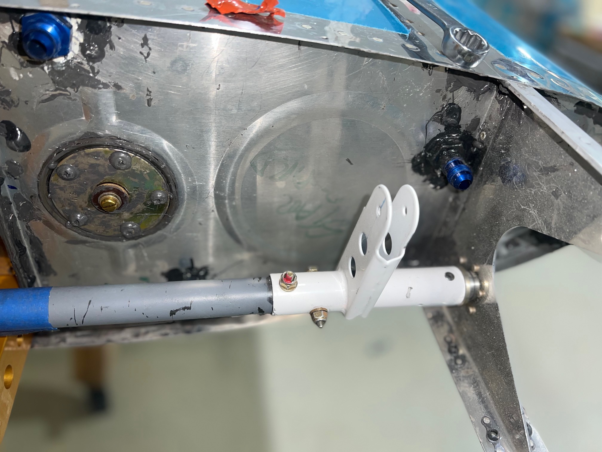
Care must be taken when plumbing the return line so that it does not interfere with the tank internal structure and the various connections in the wing root. The T1003B rib that forms the inboard end of the tank has a tooling hole at the forward end. This hole was expanded to take a bulkhead fitting when the tanks were built. See the pix to the right.
Wing Root Fuel Filters
The wing root filters are mounted vertically. Fuel flows from the tank outlet to the TOP of the fuel filter and then to the fuselage inlet from the BOTTOM of the filter. I use 150 degree fitting to make the connection to the fuel tank outlet. I will complete this line when the wings are installed.
This design means that if the tanks are about half empty, the filters can be removed with a minimum of spillage. This also avoids the need for shut off valves etc. which represent an additional point of failure and may be difficult to plumb in the tight space of the wing root.
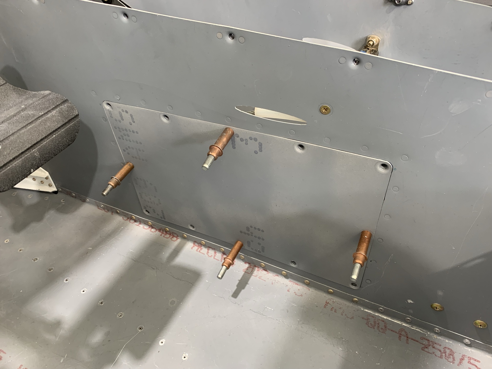
Tunnel Access
Easy access to the fuselage tunnel is key as you may need to service components located therein. I used the Airward.Com tunnel access kit to create a removeable panel on the pilot side of the tunnel. It is easiest to install this panel when building the tunnel rather than later after the fuselage is built.
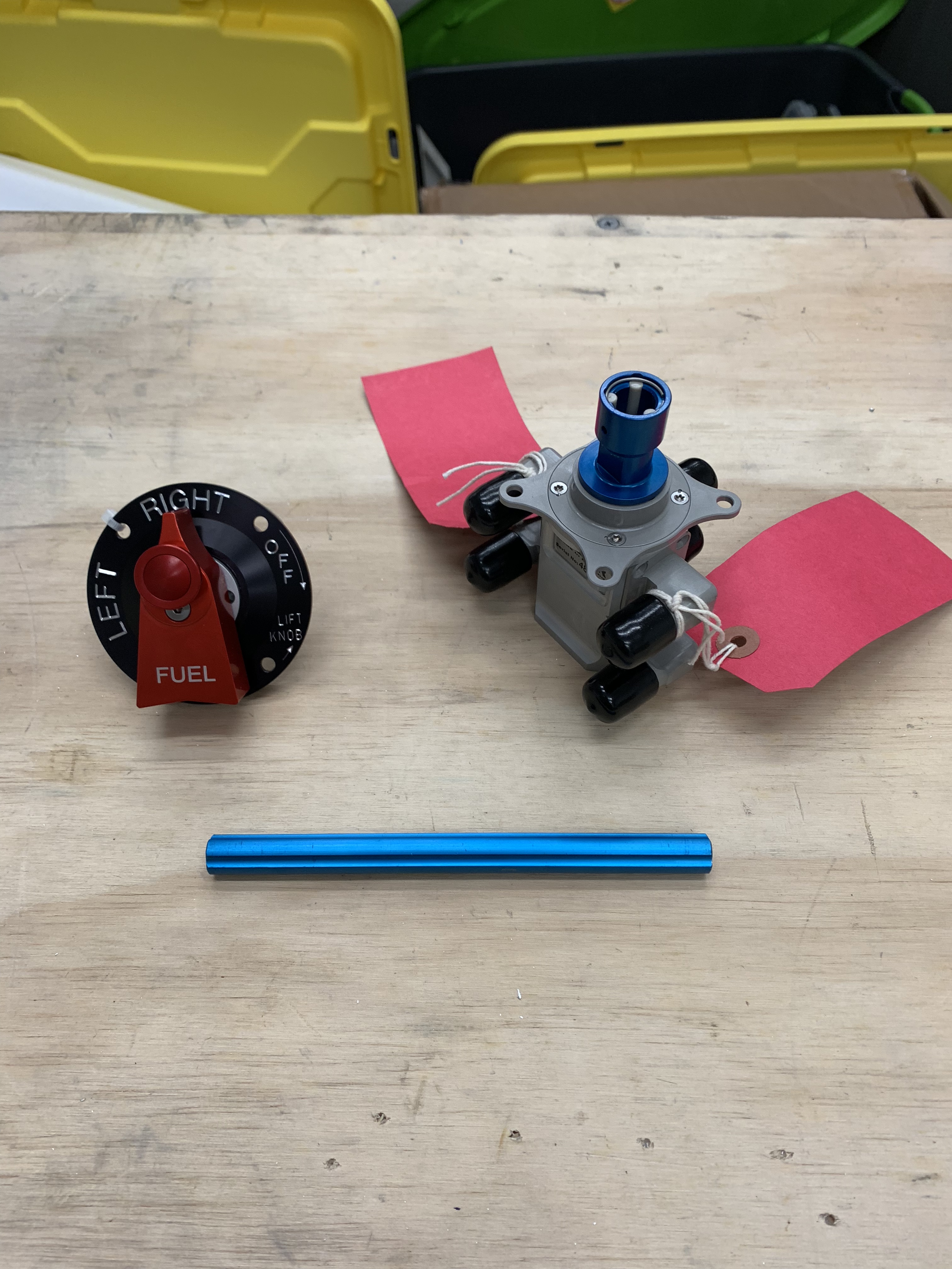
Fuel Selector Valve
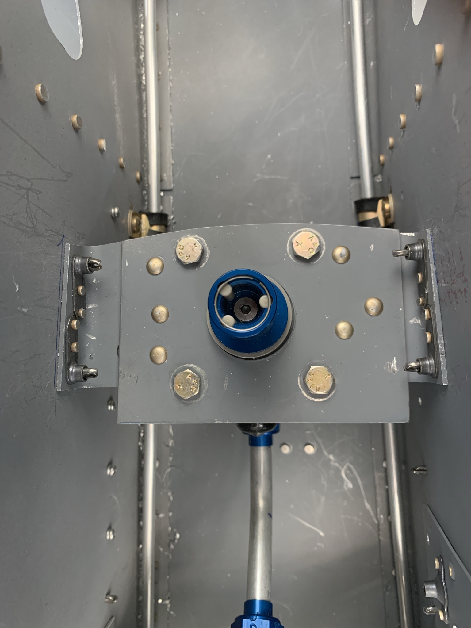
I chose the Andair duplex fuel selector valve as a replacement for the stock Van’s fuel selector valve. I used Andair valve EFS20-20-D2-TMT which has rear facing ports on the side of the valve. This is essential as tunnel clearance is very limited to the side of the valve. You will not be able to use straight port with angle fittings. You will also need two universal joints as well as an extension.
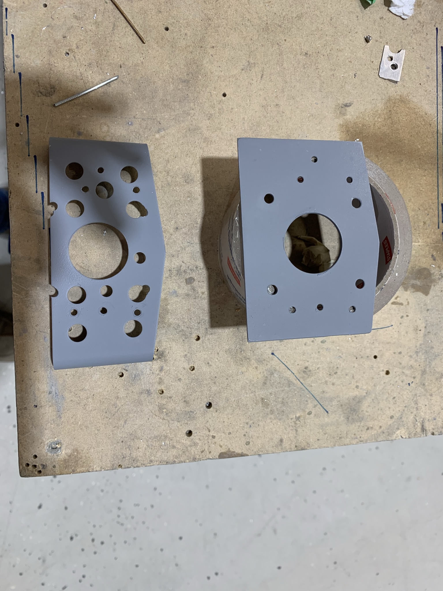
I also fabricated a mounting plate that was rivetted to the underside of the Van’s valve mounting bracket. I installed the bracket upside down low in the tunnel so that the valve was about 1/4″ above the tunnel floor. I used nutplates to install the bracket so the valve could be easily removed for service (if ever required). Note that the valve is located low in the tunnel which means a valve extension will be required to connect the valve with the selector know to be located on top of the tunnel cover.
Fuel Pump Installation
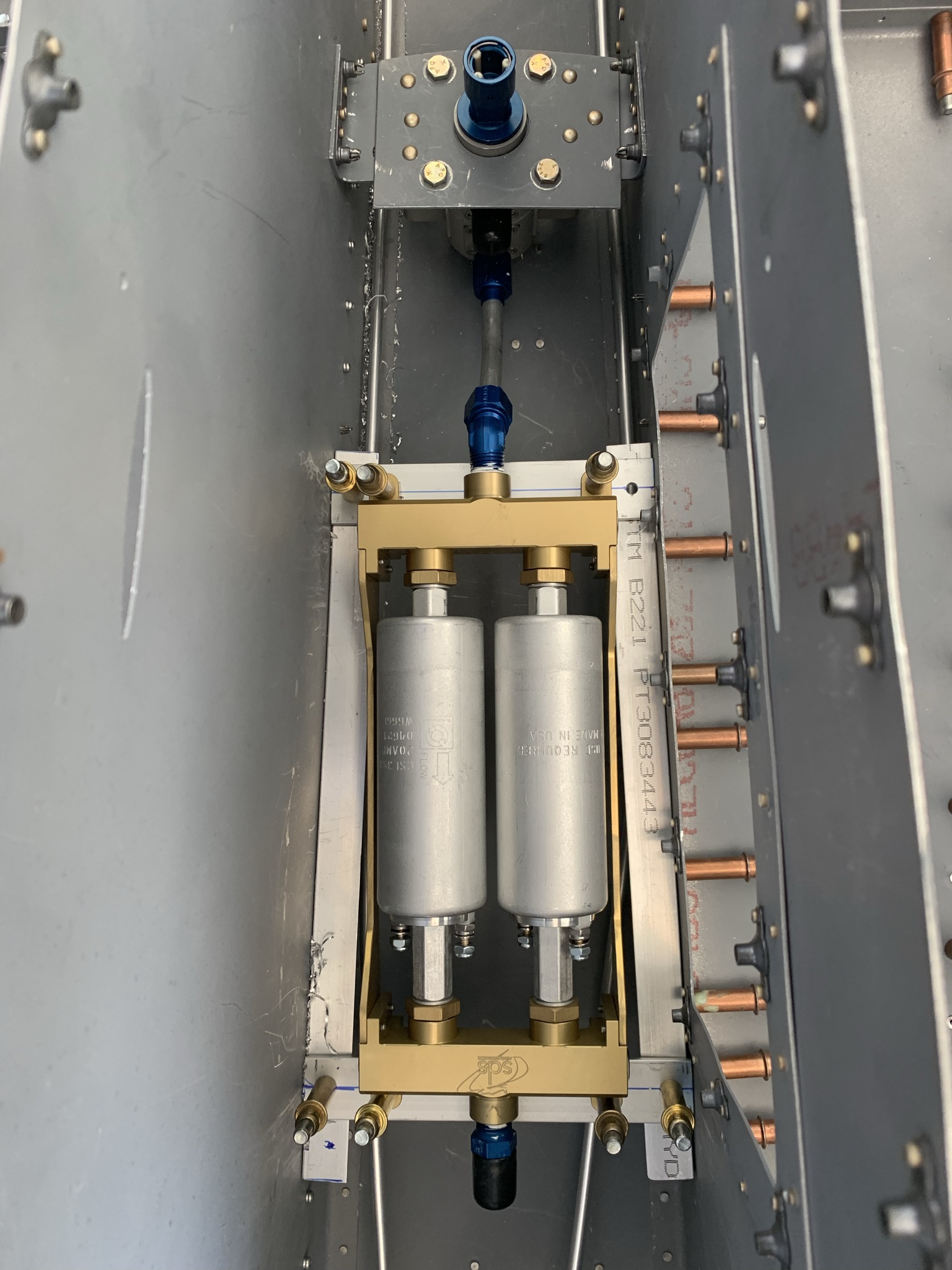
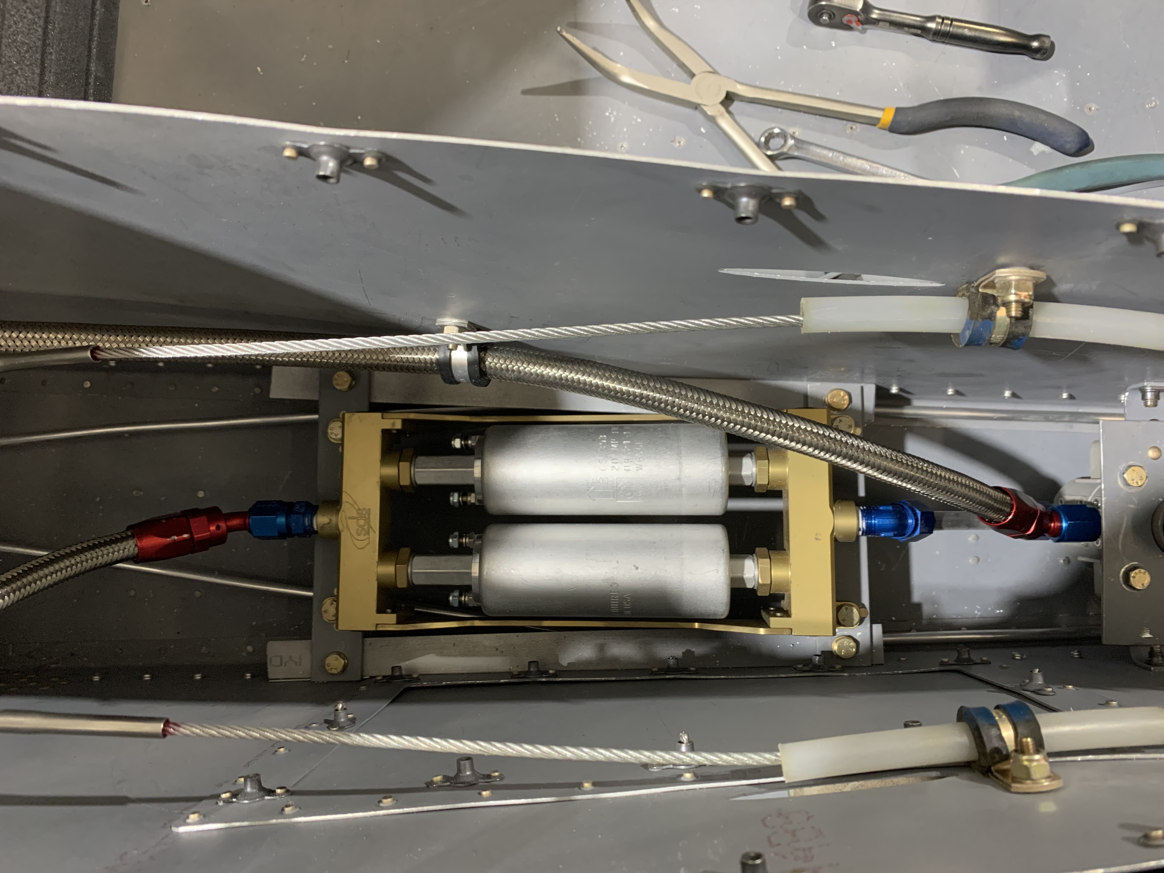
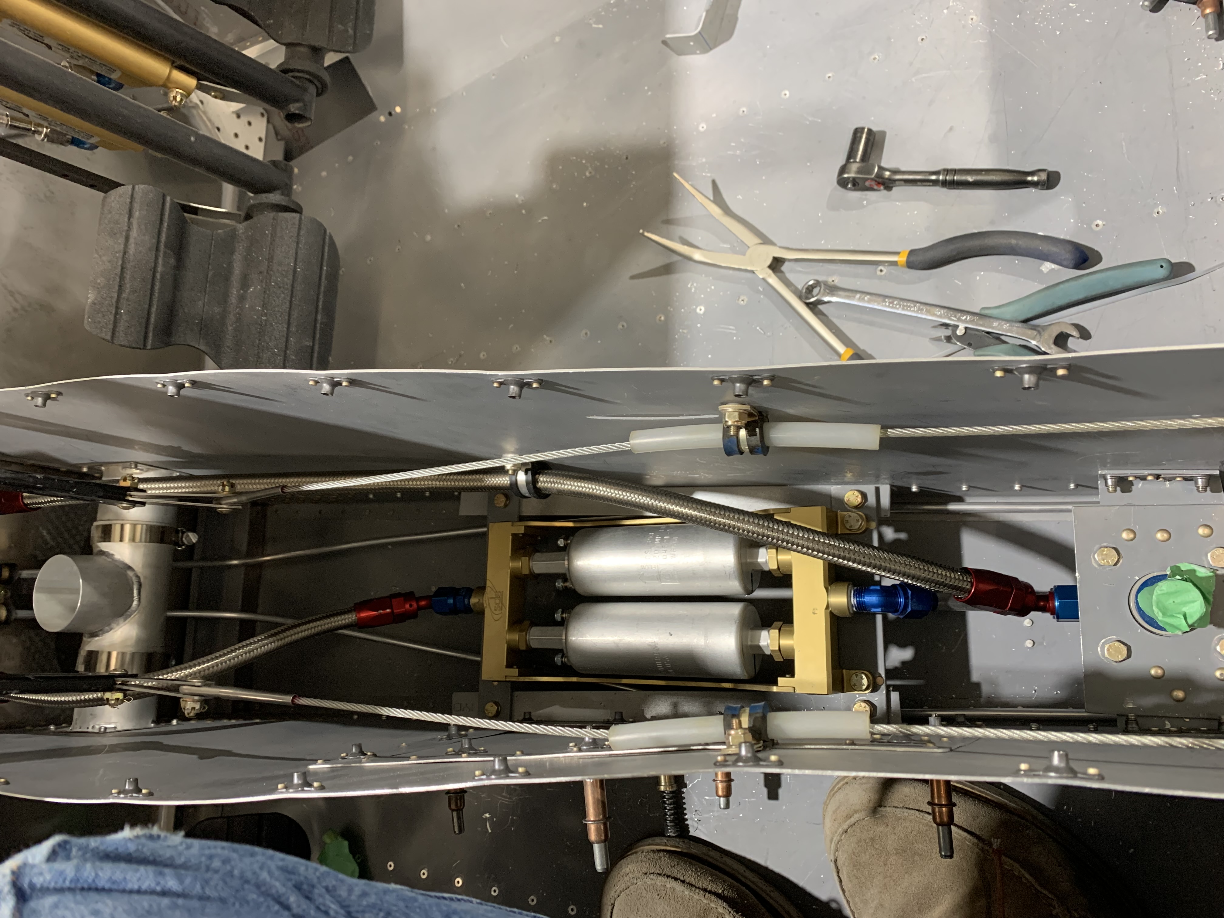
Installing the fuel pump is straightforward. I created a shelf accessible through the tunnel access panel. Nutplates were used rather than than nuts to secure the SDS fuel pump module. This makes removal of the module easy as you don’t need to get access under the module – always think about maintenance when installing components.
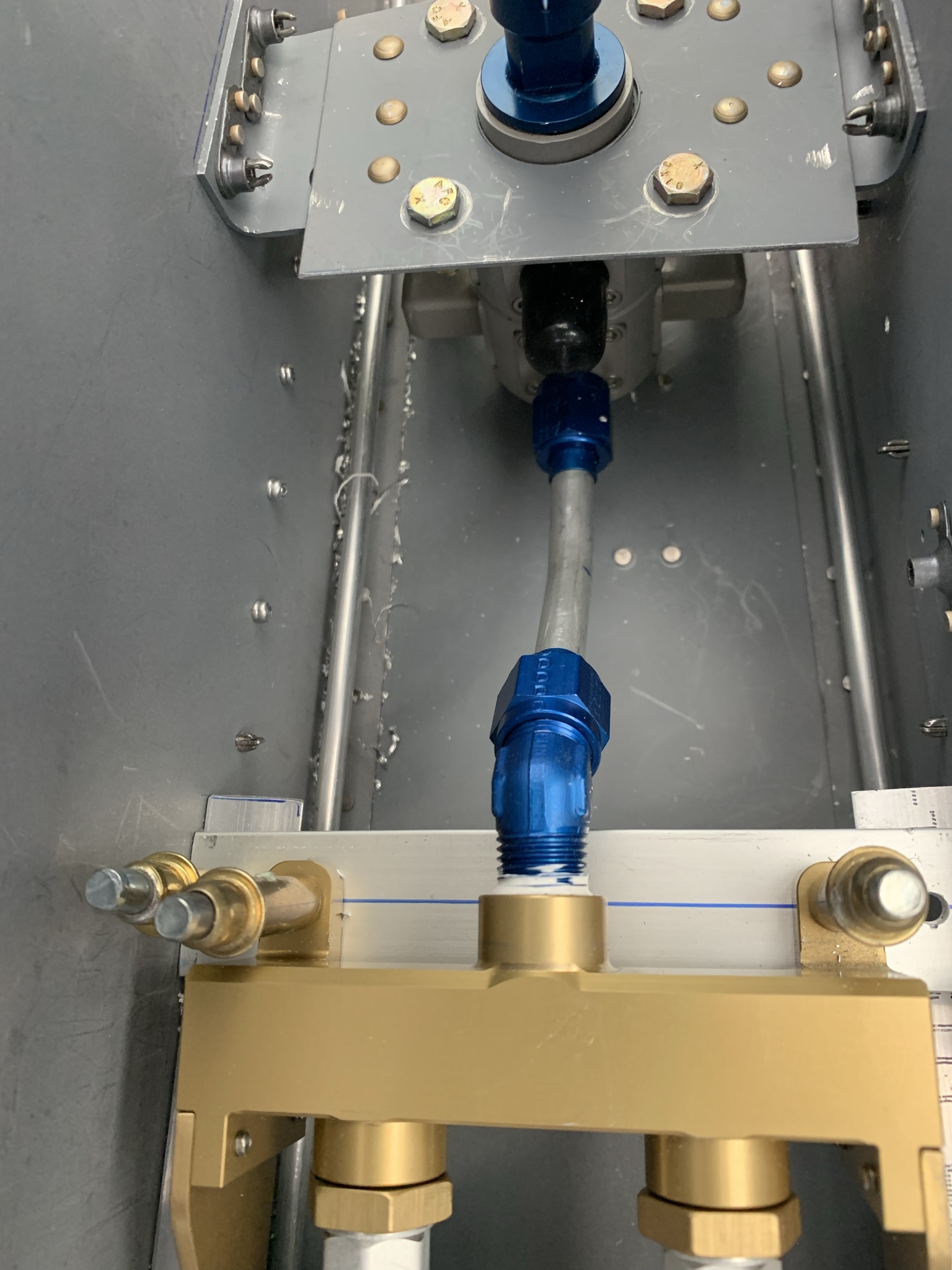
I placed the module in the tunnel and then plumbed it to the fuel valve. I then drilled the mounting holes. It would have been much more difficult to make the tight fuel line connection if the module could not be shifted slightly.
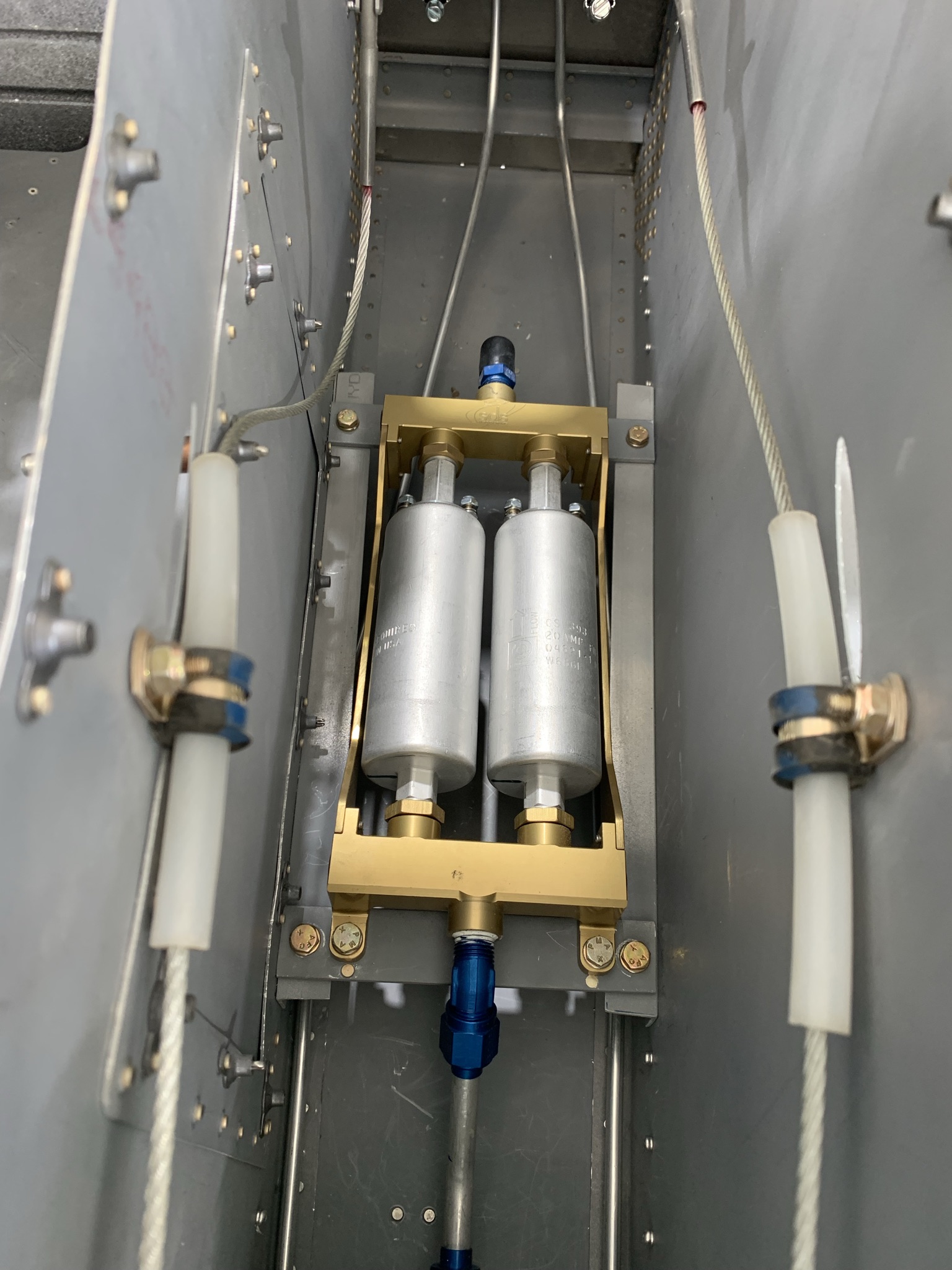
GOTCHA
As noted in the SDS documentation, there are ports in the fuel pump module that need to be tightened / sealed before installation of the module. Be sure not to miss this step.
Fuel Lines to Tunnel Sidewall & Under Seats
I used braided steel hose to make the connections to the tunnel sidewall bulkhead fittings. The distances were short and required complex bends. It was easier to use flexible hose rather than bend tubing. From the tunnel to the fuselage walls I used 6061T6 aluminum 3/8″ x 0.035″ tubing from Aircraft Spruce. It is stiffer than the Versa tubing supplied by Van’s but easily bendable over longer runs.
You will note that under the seats there are two -6 lines, one is the supply line in the stock position. Above it and held in place by an Adel clamp is the return fuel line.
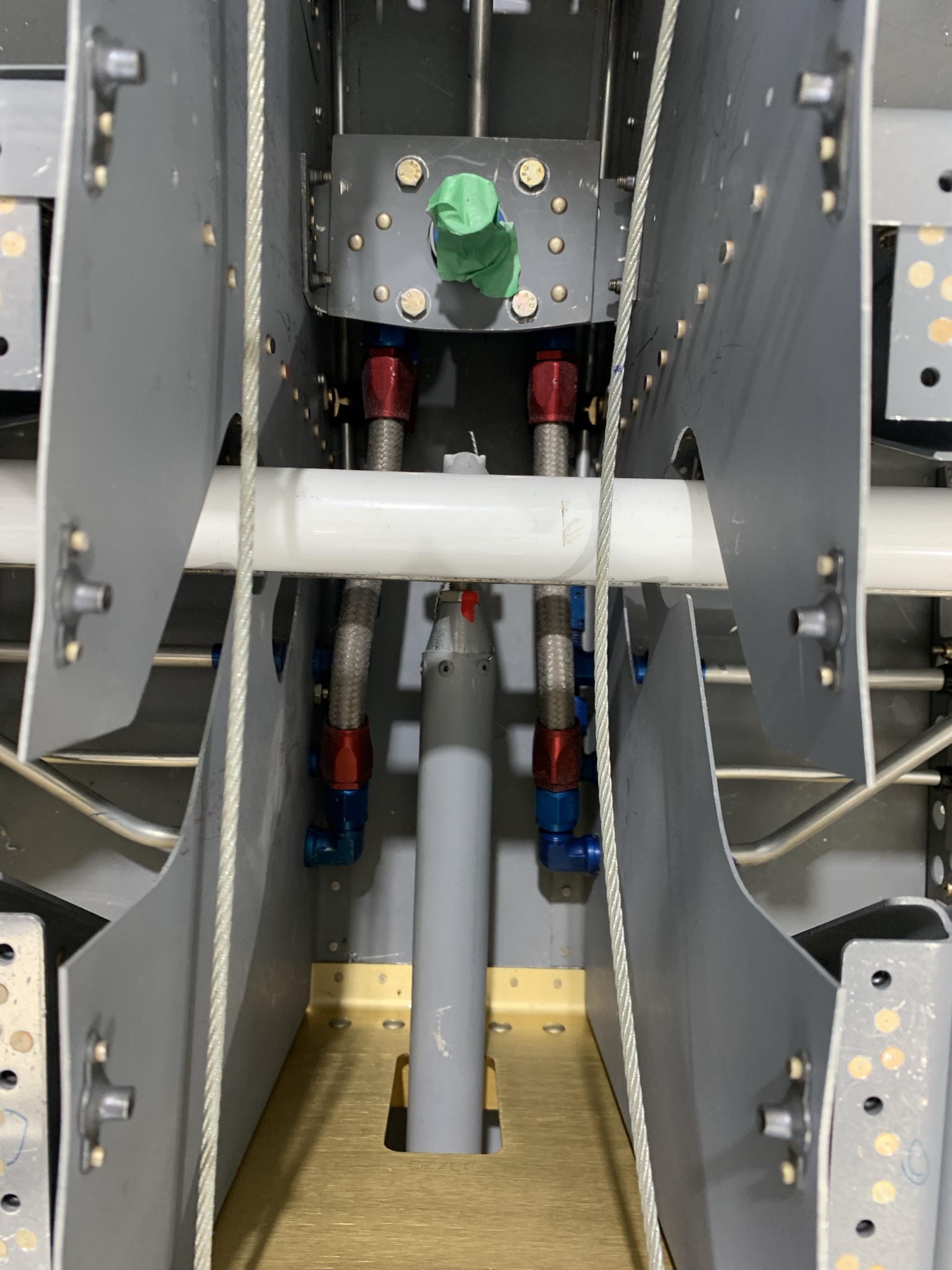
In the pix above, you can only see two of the 4 lines that go from the fuel valve to the tunnel sidewall. Two lines are hidden below the top two lines.
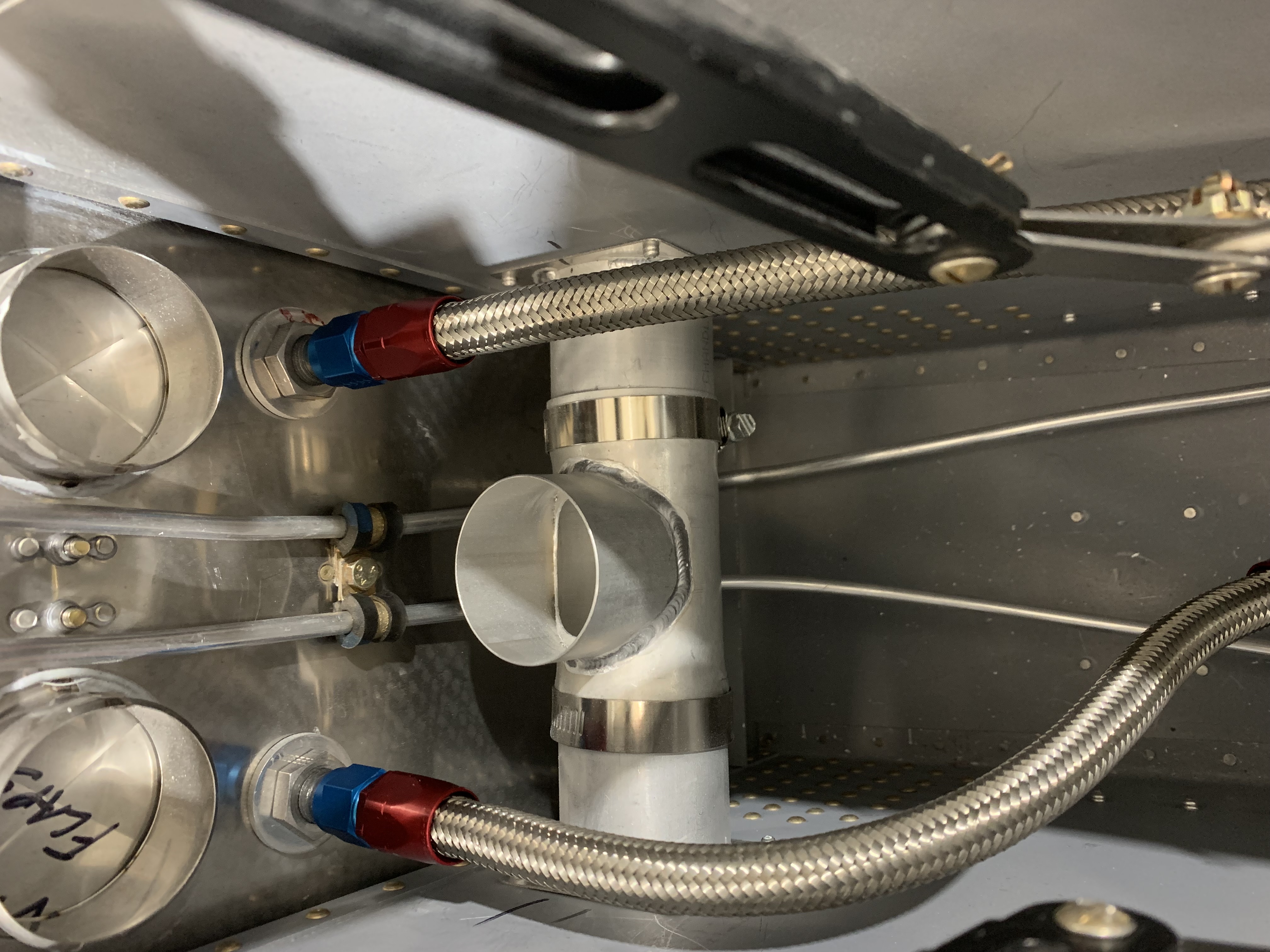
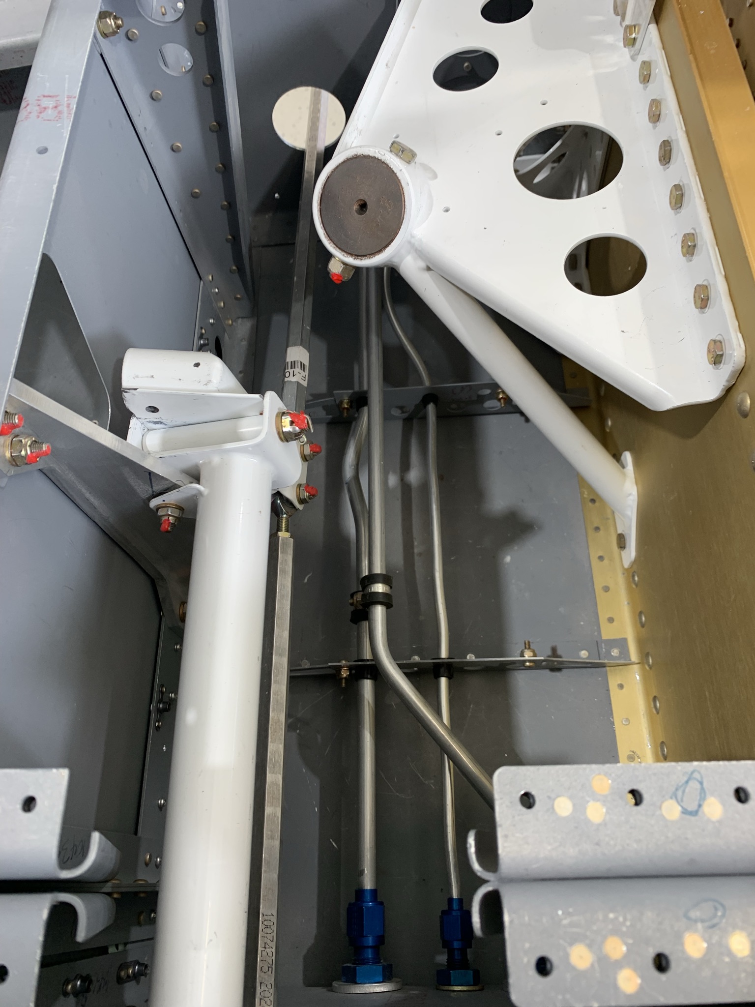
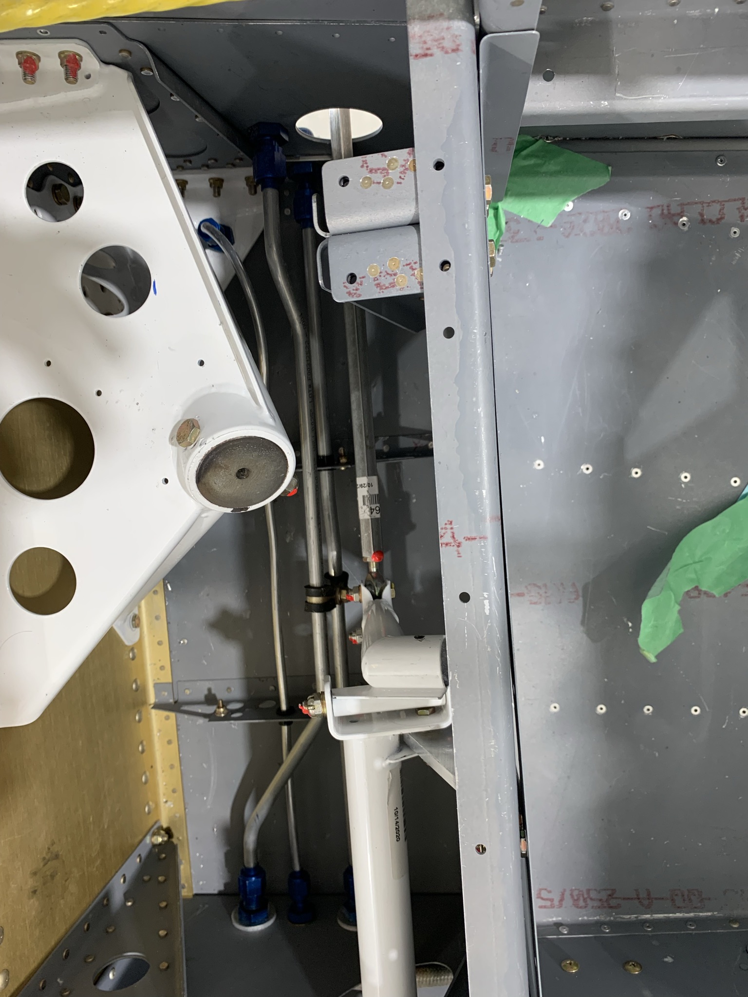
The pix above show the fuel lines that run to the firewall from the fuel pump and the return line that goes from the firewall to the duplex fuel valve. The firewall bulkhead fittings are steel. Also note that an additional hole was drilled into the right side of the firewall for the return fuel line – the stock firewall only has / needs one hole. As the return line is rather long, I secured it to the side of the tunnel using an Adel clamp. This keeps the hose well away from the rudder pedal connections and rudder cables. For those building with stock rudder pedals, you will notice that the pedal connections are inside the tunnel. This is because I am using the Control Approach aftermarket pedals. They are infinitely nicer than the stock pedals (IMHO).
FWF, all the fuel lines were constructed using Aeroquip braided steel hose and fittings. The lines were fire sleeved. Oetiker clamps were used to hold the fire sleeve in place.
On trick I learned from another builder was how to seal the ends of the fire sleeve. You can buy a sealant for this purpose but it is fairly expensive. A simpler solution was to take some Red Permetex RTV and thin it with lighter fluid until it is more like paint than paste. Simply dip the end of the fire sleeve in the “paint” and you are done. Any excess on the outside of the fire sleeve is wiped off.
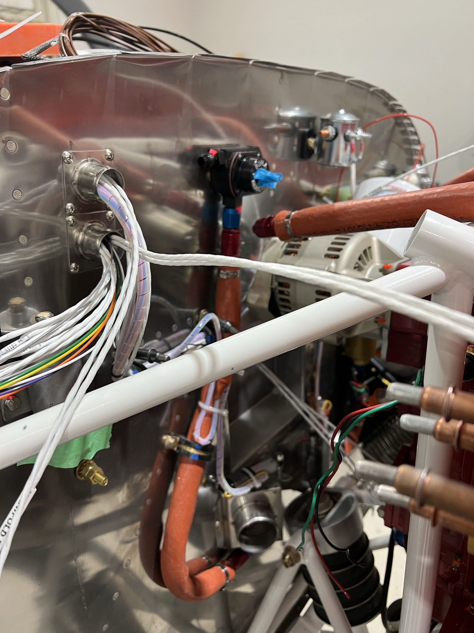
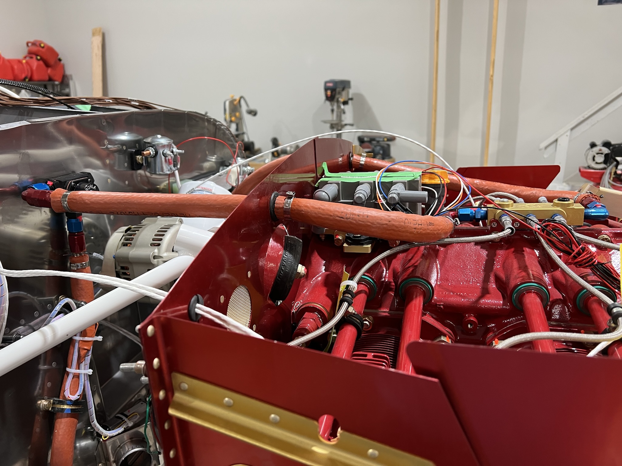
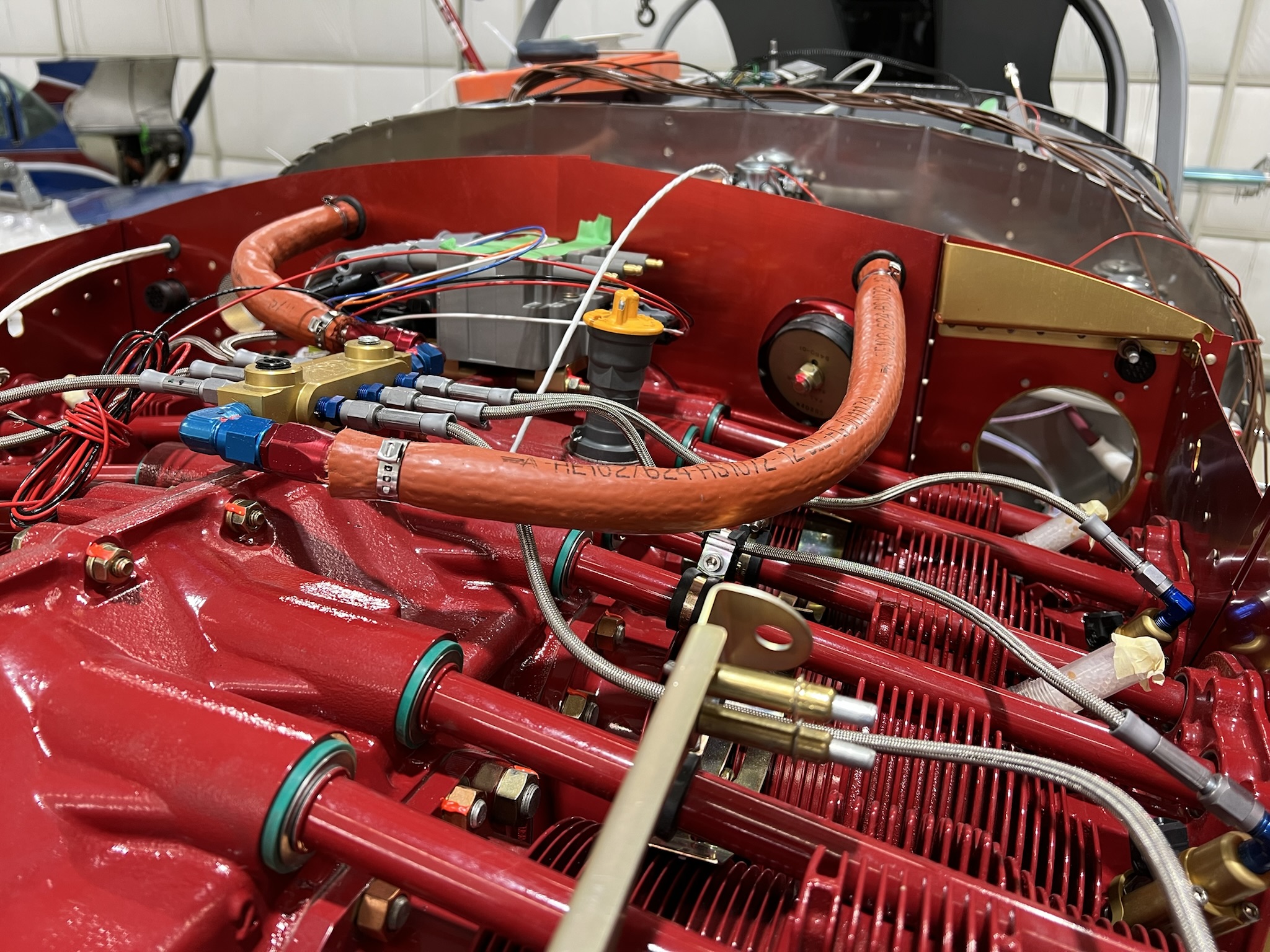
The pix above show the FWF fuel lines (the line to the Borla fuel pressure regulator is disconnected). I used rubber grommets to make the baffle passthrough. The grommet hole was sized to allow the hose fitting / fire sleeve to barely pass through. The hole is too small to allow the Oetiker clamps to pass through so I slipped these on and installed theses after the hose was installed. You might notice that the fire sleeve is broken where the grommet is. This allowed a smaller grommet to be used. The grommet was split and installed after the hose was installed.
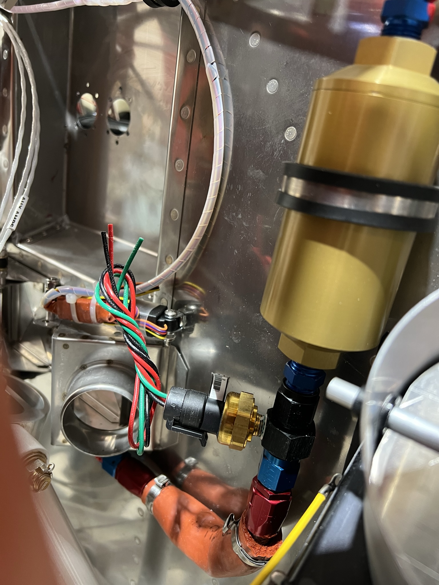
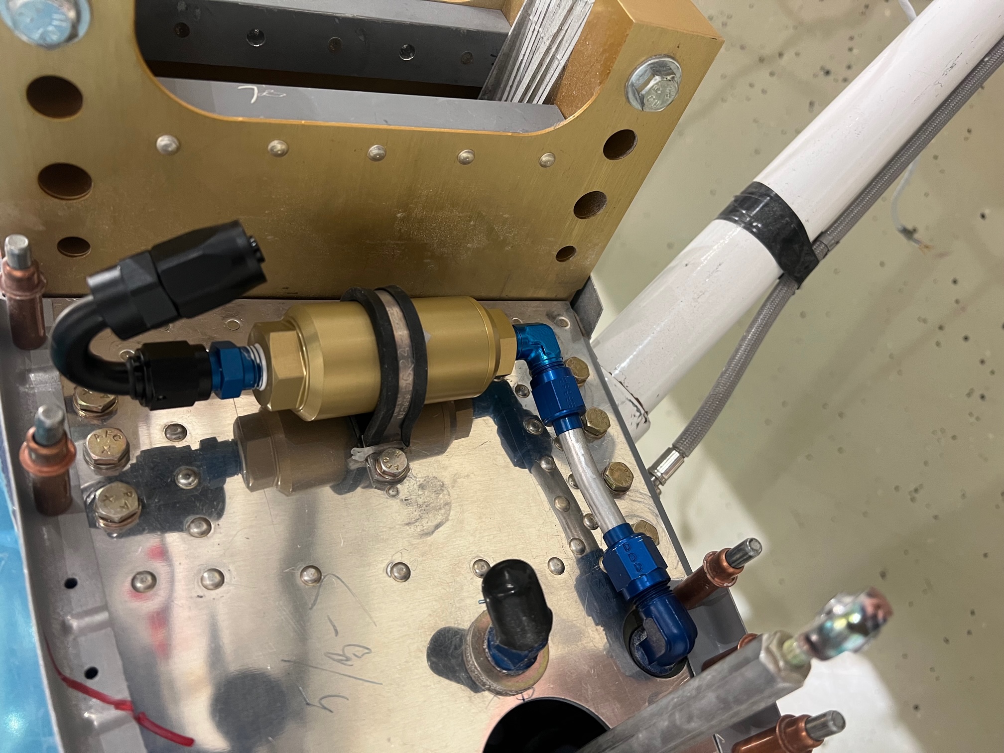
The pix to the right shows the fuel supply line to the engine with the fuel pressure sensor and fuel filter installed.
The fuel pressure sensor was installed before the fuel filter deliberately. In the event that the filter becomes partially blocked, there should be an increase in fuel pressure as the fuel pumps work harder to overcome the blockage. The Garmin G3X will be programmed to present a fuel pressure warning if the fuel pressure becomes abnormally high.
The G3X fuel pressure sensor is plumed into the line using a 1/8 NPT gauge port (available at most speed shops). It has a female end on one side and a male end on the other.
To be clear, however, the above is not meant to replace periodic servicing / examination / cleaning of the fuel filters.