The Hall Sensor Install is not complicated but does require attention to detail. As you are aware, the Hall sensor senses magnets embedded in the flywheel which in turn tells the ECUs where the crankshaft is in its rotation. Without this information the ECUs would not know which spark plugs to fire or which injectors to open. Be sure to follow the SDS installation instructions to the letter paying particular attention to the gap between the flywheel and the sensor.
The mounting bosses for my Hall sensor where installed by Aerosport Power when my engine was built. I only had to confirm that the gaps was correct.
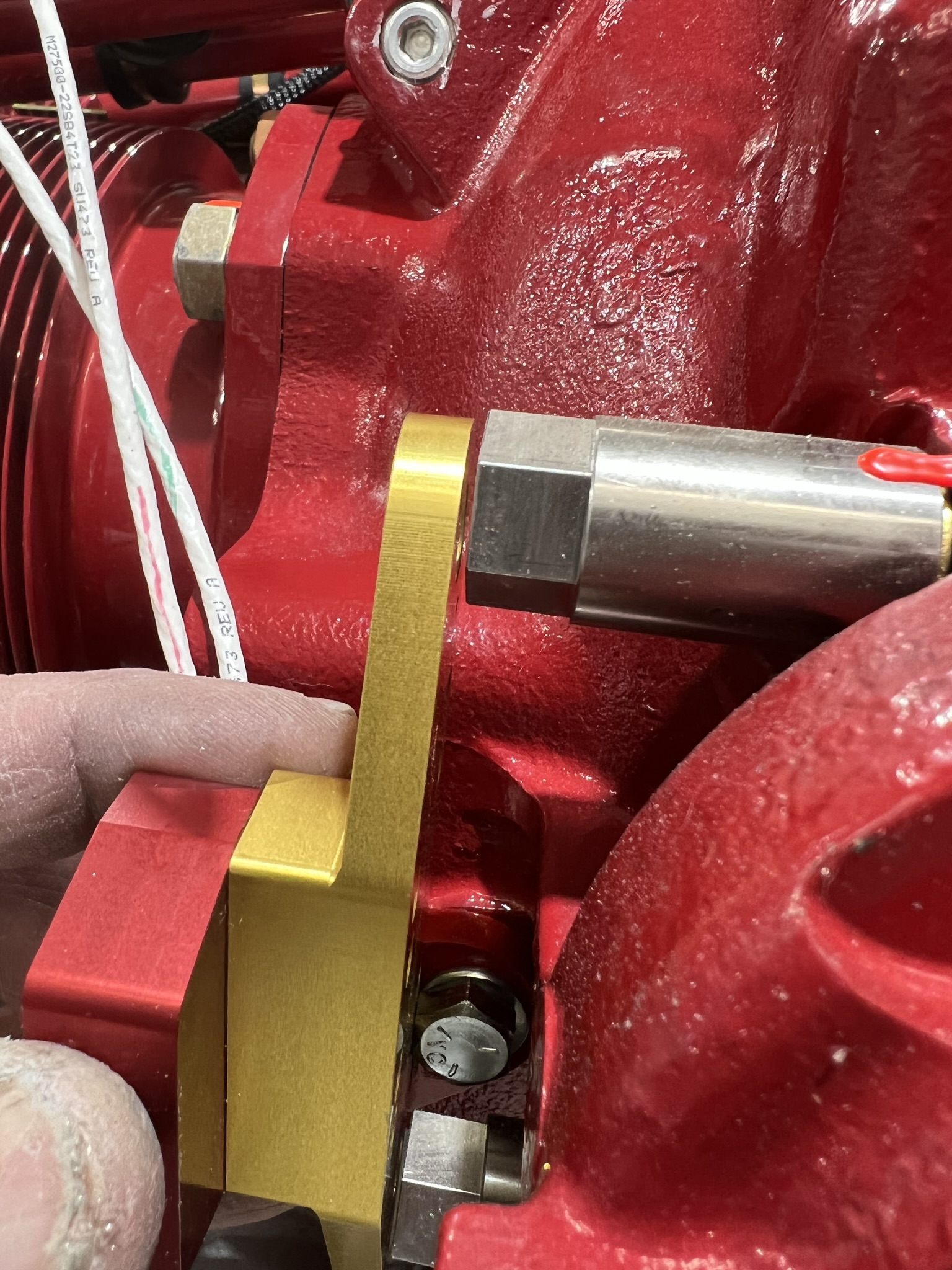
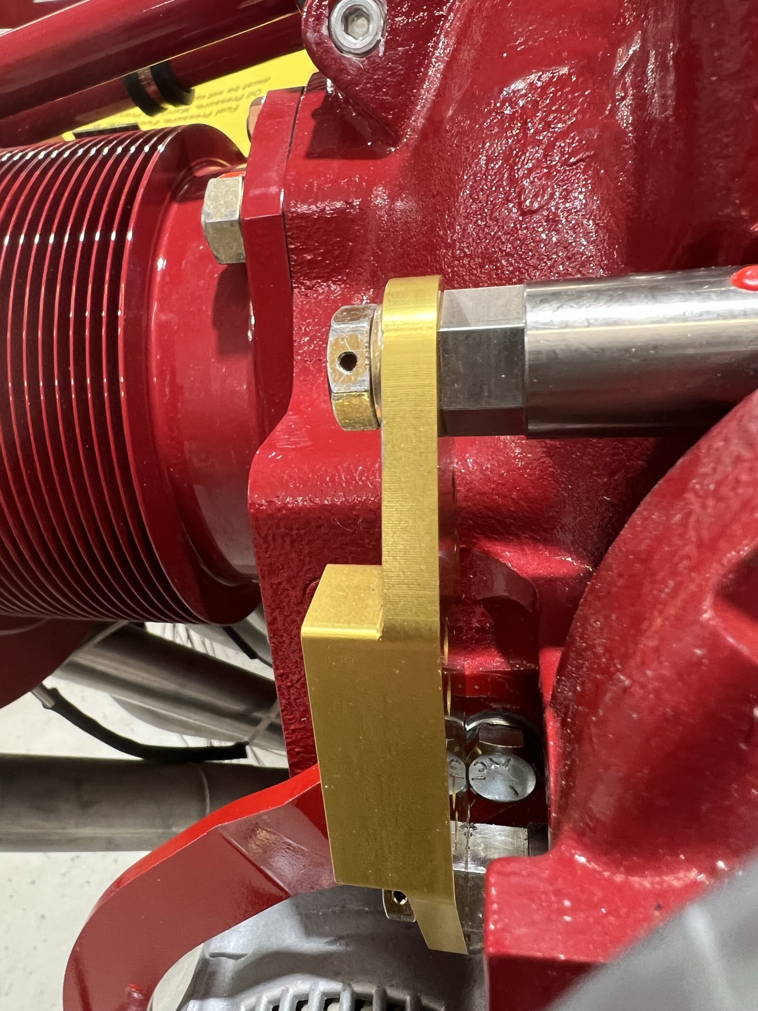
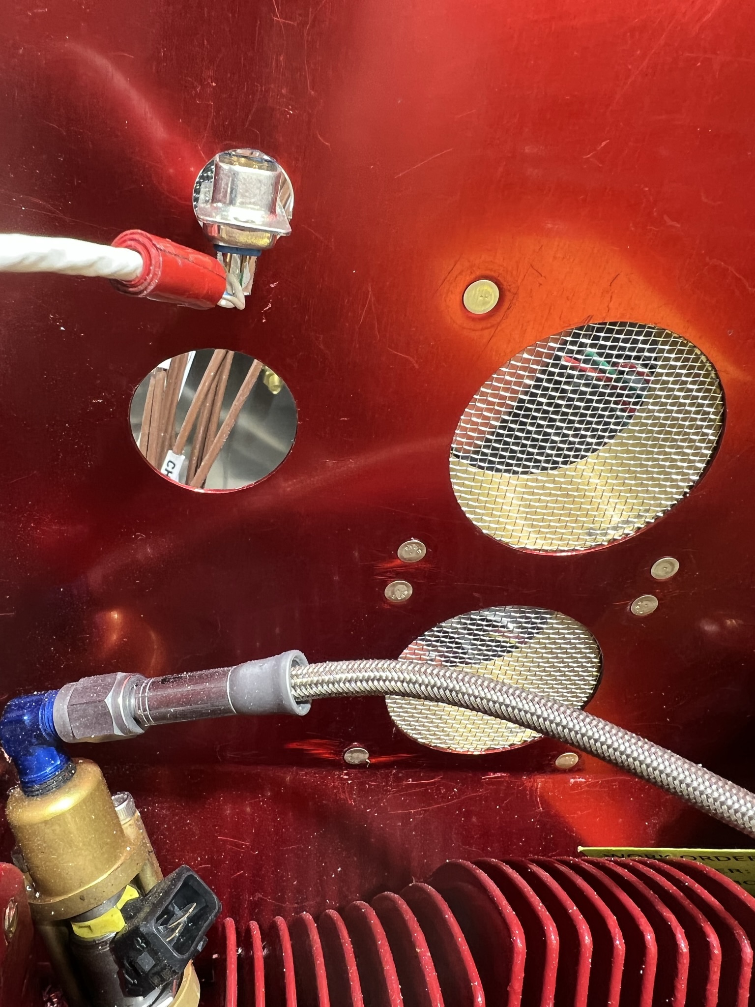
I did have a small problem when I tried to install the sensor after the alternator mounting arm was installed. The pix to the above left shows a silver bolt in the bottom middle of the pix. This bolt holds the alternator arm. However, the edge of the bolt head interferes with the Hall sensor bracket. The reason for the interference in my case) is that the alternator arm is thicker than expected as is the lock washer. Consequently the head of the bolt is too high (for the Hall sensor bracket).
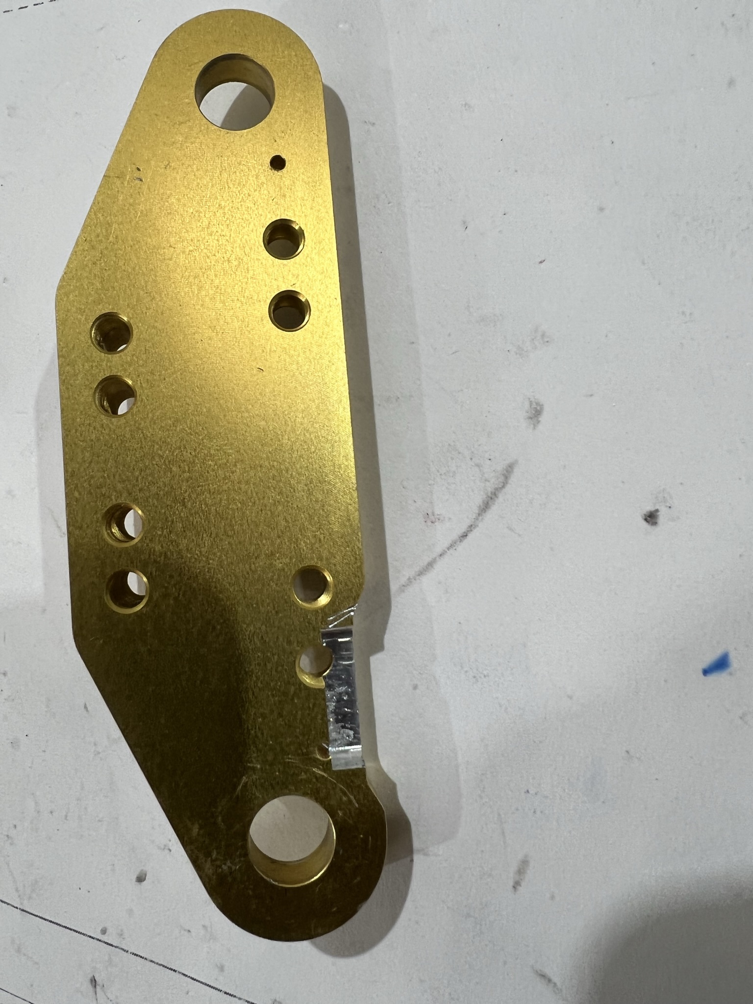
To correct this problem I notched the bracket to allow additional clearance for the bolt. This I did only after consulting SDS.
A final note, BE SURE TO SAFETY WIRE THE SENSOR MOUNTING BOLTS.
If you decide to leave the D-Sub connectors on the Hall sensor leads, you will have to decide how to get the connectors through the rear engine baffle (alternatively you could run the leads under the engine but I chose not to).
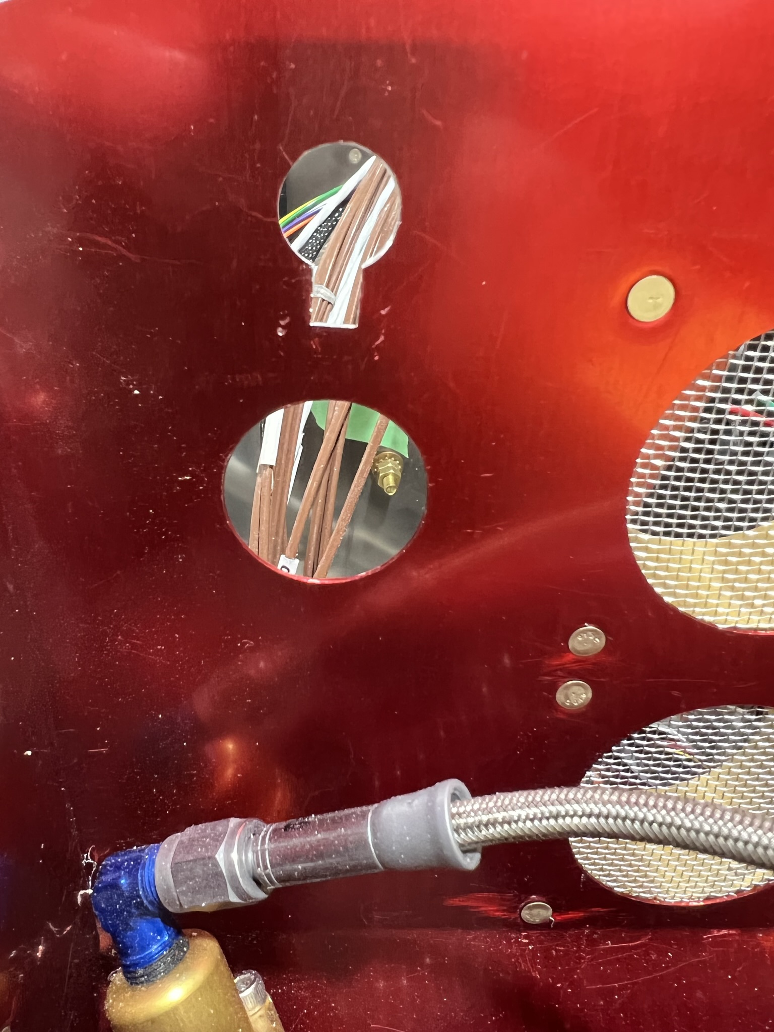
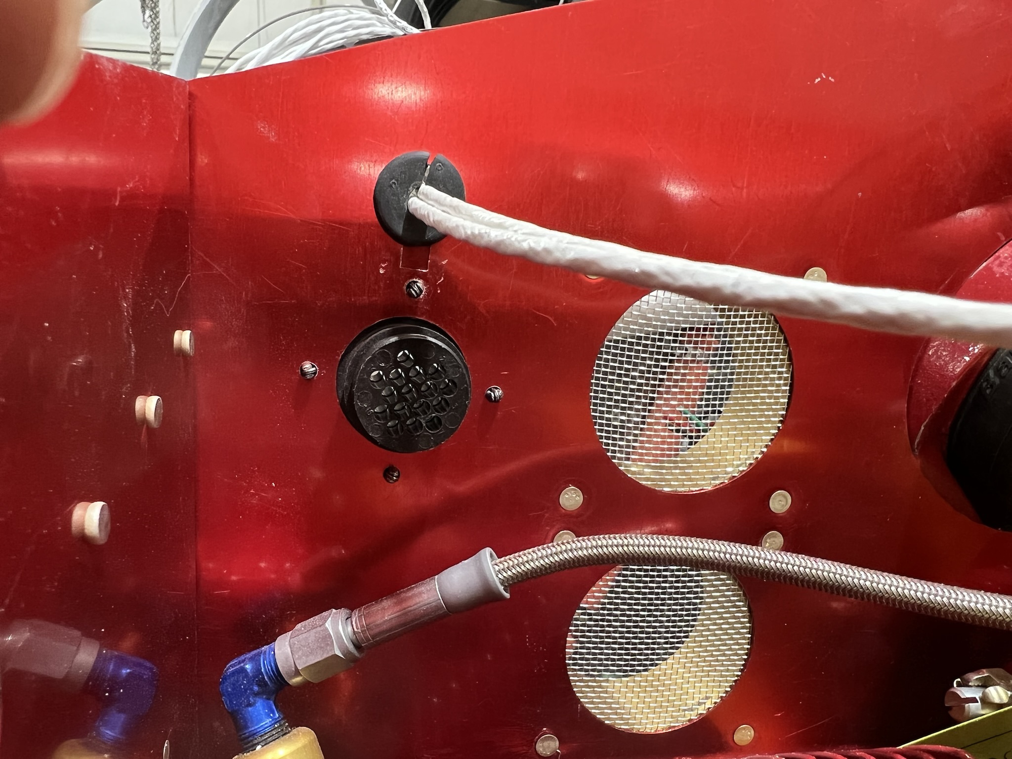
My solution was to make a hole sized for a small rubber grommet that would hold the leads. Using a nibbler, I notched a keyway way into the hole. This allowed me to push the D-Sub through the hole. The edges are sharp so be careful that wires are not damaged. To complete, the grommet was split and installed. As a final step (it is hard to see in last pix) I made a small tab that covers the keyway. It installs behind the baffle and uses one of the holes drilled for the CPC connector flange.