Each of the injectors (6 on the IO-540) have two wires. One wire is connected to the appropriate colour coded injector wires from the injector relay box the other to the injector power source. The injector wires are both white so either one can be connected to the power source and the other to the coloured wire. Keep in mind that the coloured wires from the injector relay box control the injectors by providing a ground when the injector is active. Consequently each injector is always connected to a power source.
For this installation, each injector power source was separately fused. Circuit breakers were not used for the injectors as it would seem very risky to reset a injector that failed.

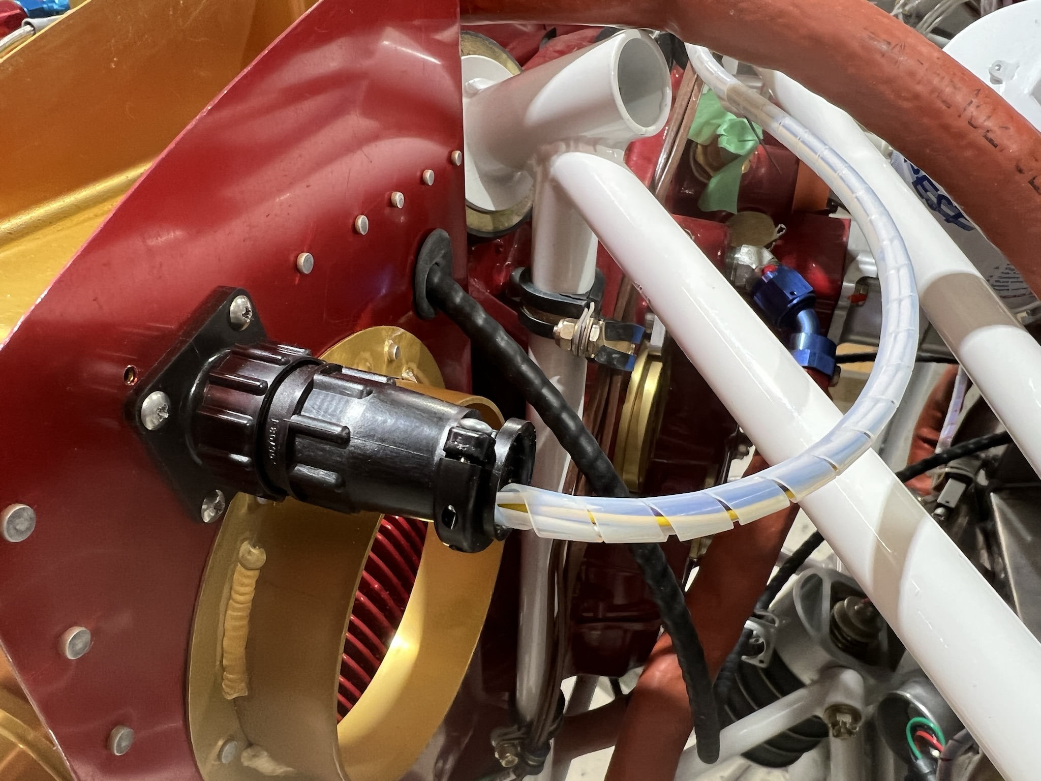
In the pix above you can see the starboard CPC (circular plastic connector) connector used to connect the coloured wires from the injector relay box to the injector leads. It is in the middle left side of the pix. This CPC connector is also used to make the connections from the coil pack mounted atop the engine to the ECU coil pack trigger wires as well as the coil pack power & ground.
A 14 pin CPC was used
– 6 pins used for the injectors on cylinders 1,3 & 5
– 3 pins for the coil pack triggers
– 2 pins for the coil pack power and grounds.
Three pins were unused.
A 9 pin CPC was used to connect the 6 injector wires for the port side cylinders (2,4 &6).
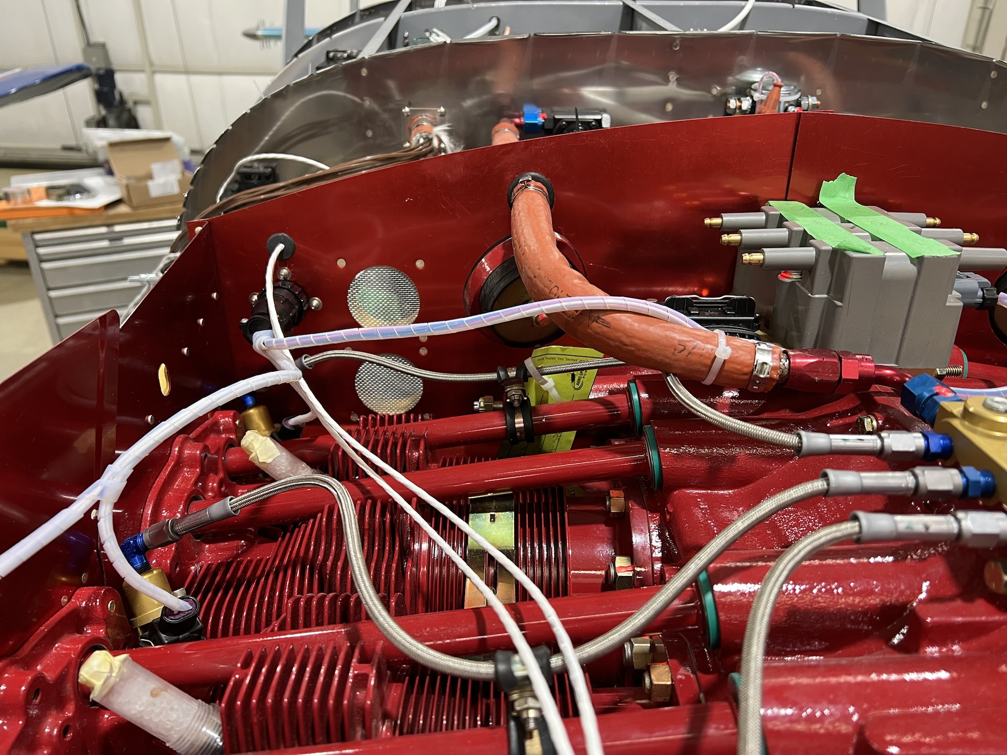
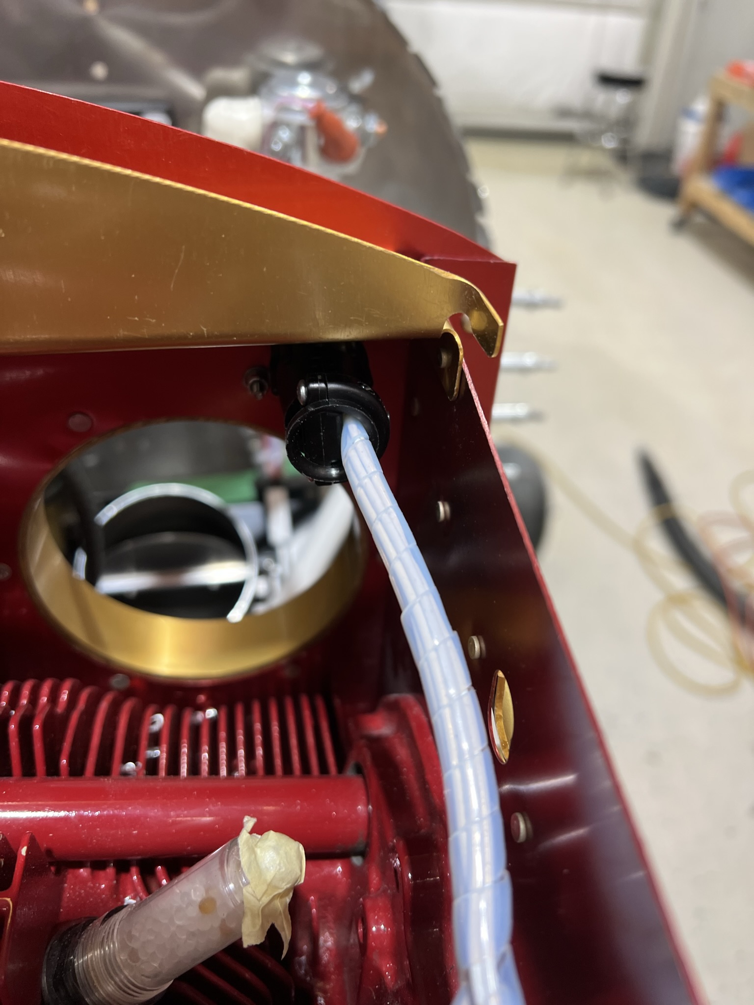
You may notice that temperature rated spiral wrap was used to gather and protect the various wires. Ultimately, the wires will be attached to the baffles.
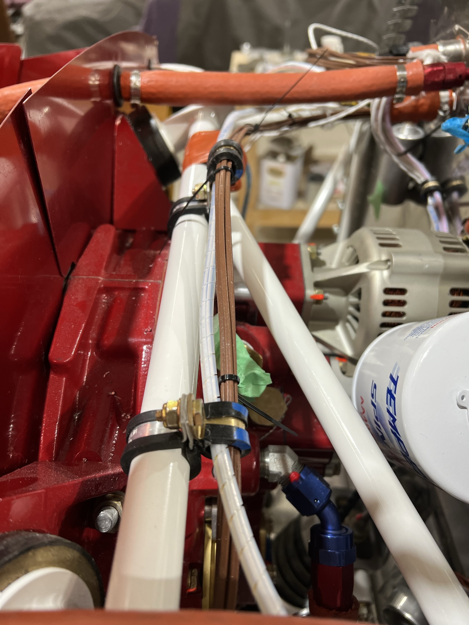
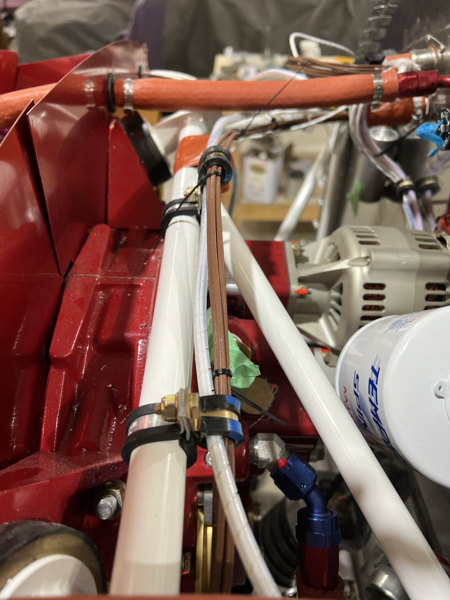
The pix above shows the other end of the port CPC connector. The CPC back shell provides stress relief for the wires. The last two pix shows how the spiral wrapped injector wires are run across the back of the engine mount to the firewall penetrations found on the starboard side of the firewall.
It is of critical importance that all SDS wiring be protected against chaffing and vibration. Be sure to have proper stress relief at all connections.