As noted elsewhere, the SDS system employs a number of engine sensor these being:
- 1 Throttle Position Sensor (TPS)
- 2 Manifold Pressure Sensors (MPS)
- 2 Cylinder Head Temperature Sensors (CHT)
- 2 Outside Air Temperature Sensors (OAT)
- 1 Oxygen Sensor (optional)
These sensors use Weatherpack connectors to make the required connections with the SDS wiring harness. The challenge for the builder is to make these connections in a manner that withstand the harsh environment FWF.
Depending on the avionics suite being installed, there are other sensors, used by the avionics, that have these same challenges.
In my install I chose to use Weatherpack connectors throughout. I also used 3:1 ratio double wall shrink wrap to protect the wires. I am quite pleased with how this technique protects the small 20-22ga harness wires.
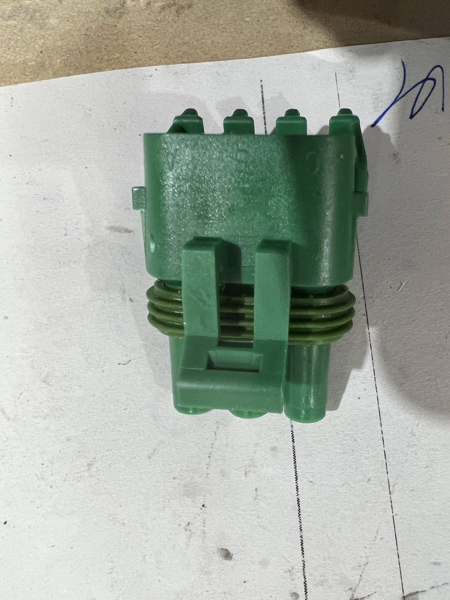
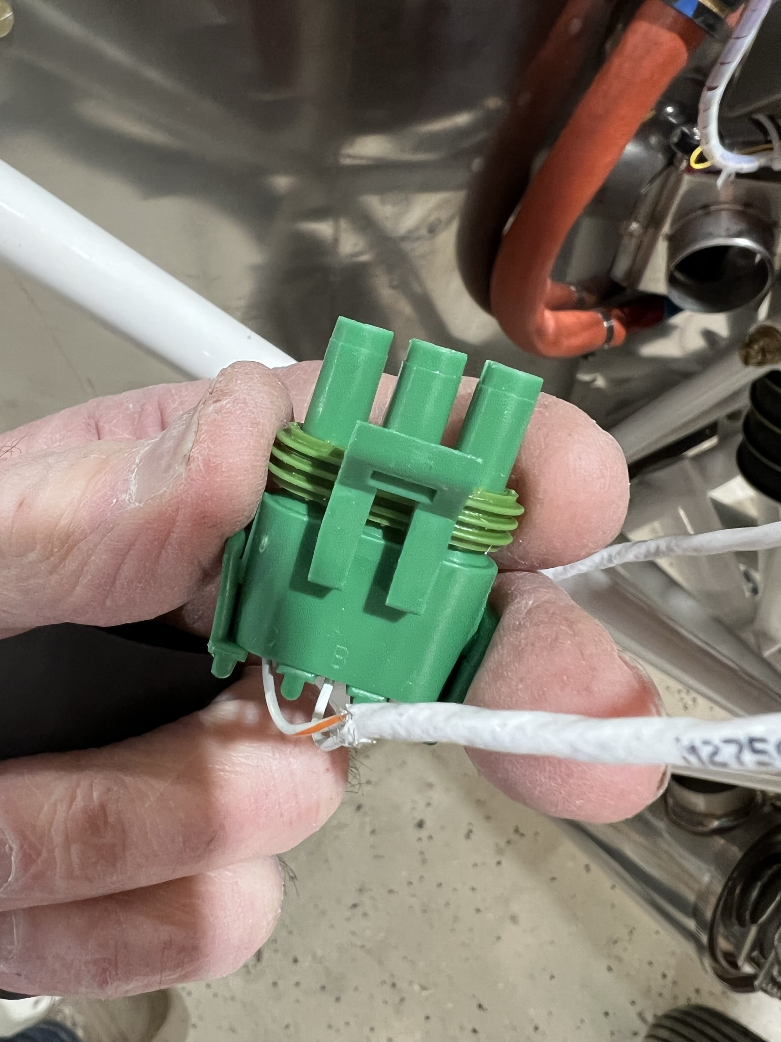
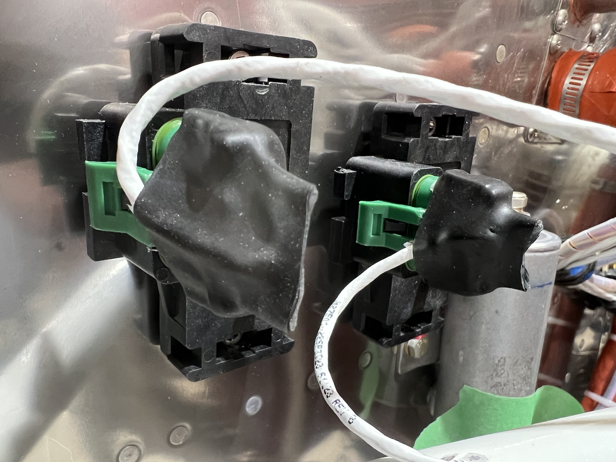
The pix above show one of the MPS connectors and what it looks like after the harness wires are installed. As you can see, the wire size is quite fine (22 ga). To protect the wires, the harness lead was folded over the connector and shrink wrap installed from the rear. The pix on the right shows the two MPS sensors installed / connected to the sensor module. The shrink wrap provides stress relief for the connections. The shrink wrap that I used has an adhesive inside so I was able to pinch the end closed thereby further protecting the connections. Once the shrink wrap cooled, it became very stiff – exactly what I wanted as the fine wires are now completely sealed.
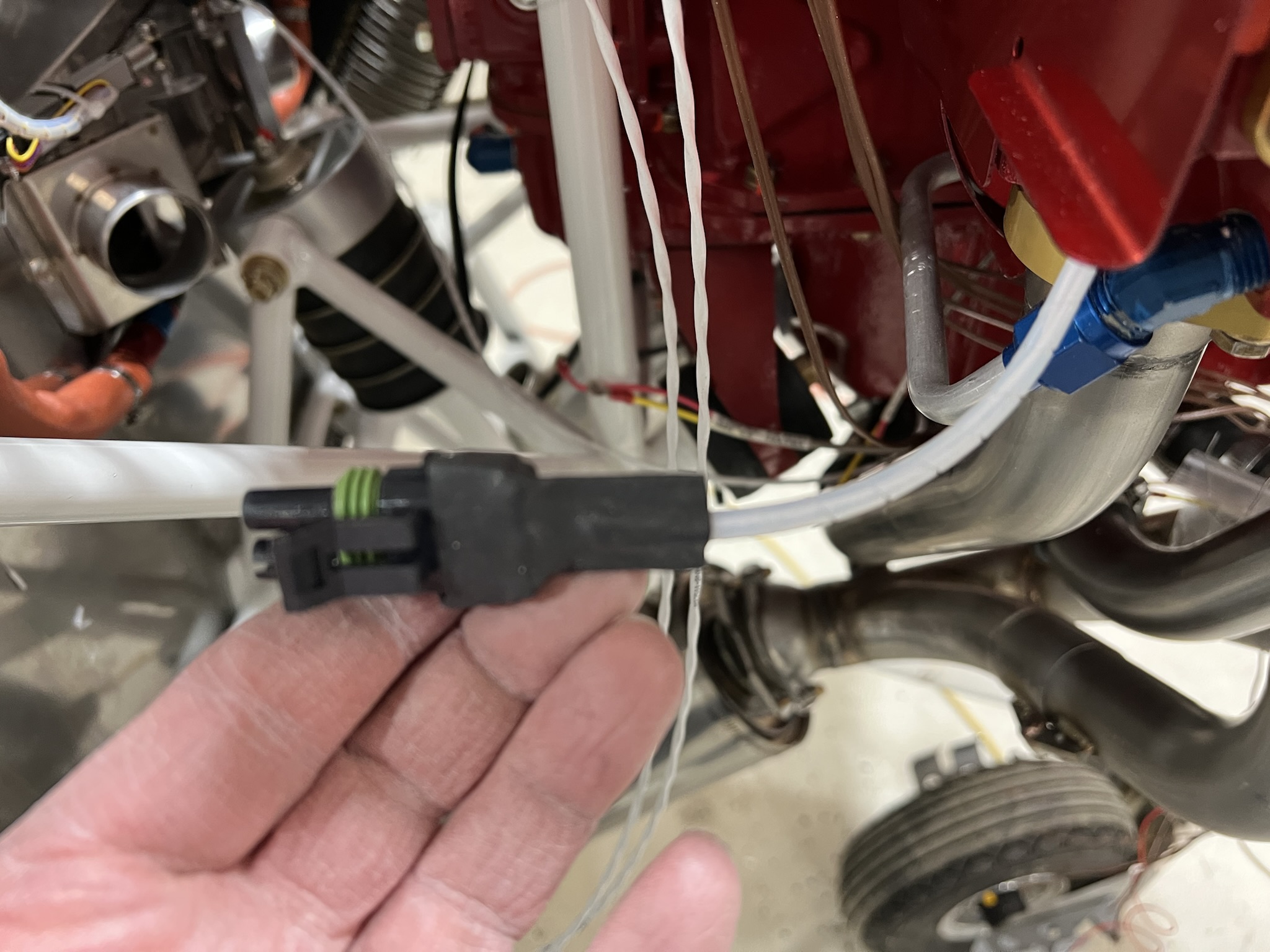
Note that an Adel clamp is used to support the wire running from the #3 cylinder. This helps protect / support the coming from the sensor. I plan to add a cone of RTV sealant to the sensor connection to provide additional stress relief.
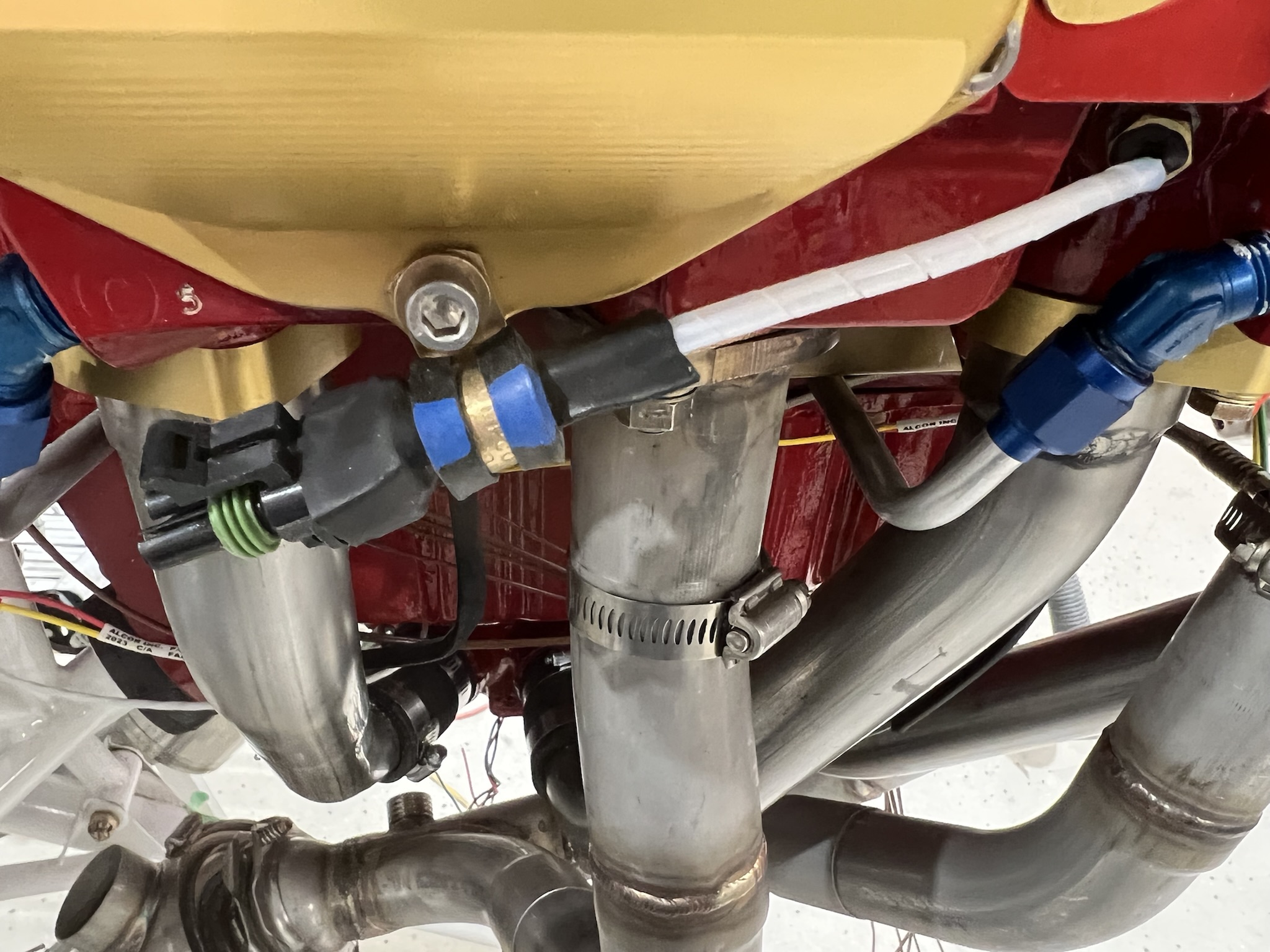
The connector coming from the #5 cylinder will be secured to the oil return line. The pix of this sensor gives a somewhat better view of how the shrink wrap was installed.
The same technique was used to connect the G3X fuel pressure, oil pressure, oil temperature and MPS sensors to the G3X wiring harness.
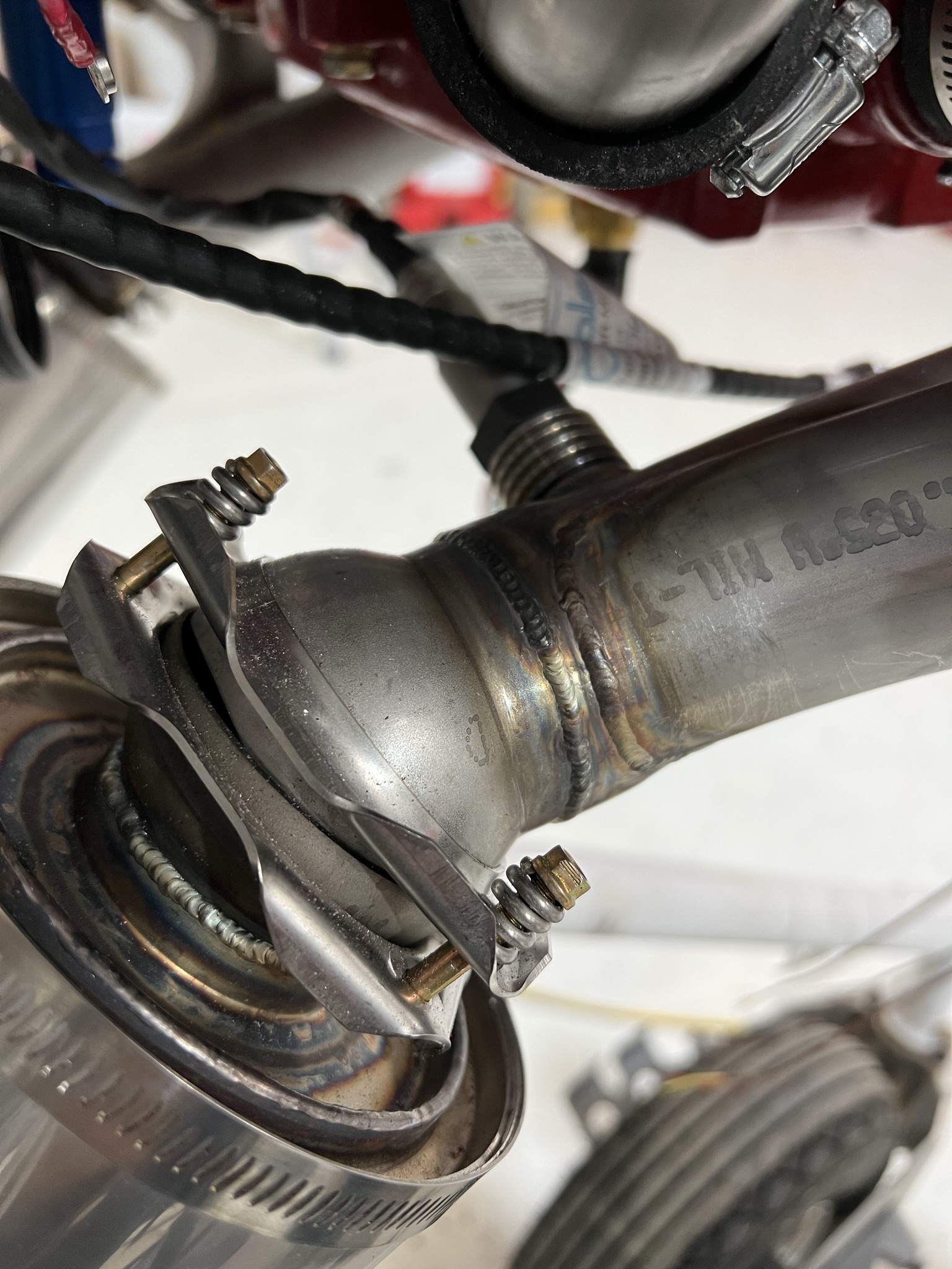
An optional oxygen sensor can be installed if desired. If you look closely at the first pix above, you will see a “bung” that was welded onto the starboard exhaust collector. The oxygen sensor is installed using this bung. The bung located just after where the three exhaust tubes join into one. Note that the bung needs to be to be within +/- 60 degrees of vertical so that water will drain from the sensor.I installed the 14point7.com Lambda 2 controller using a Bosch 2 sensor. The pix to the right shows the O2 sensor installed in the exhaust bung.
Lead in 100LL fuel is hard on the sensors especially during engine break-in when very rich fuel mixtures are required. I plan to remove the sensor and blank off the bung until after break-in is complete. Once break-in is complete, the O2 sensor will be reinstalled.
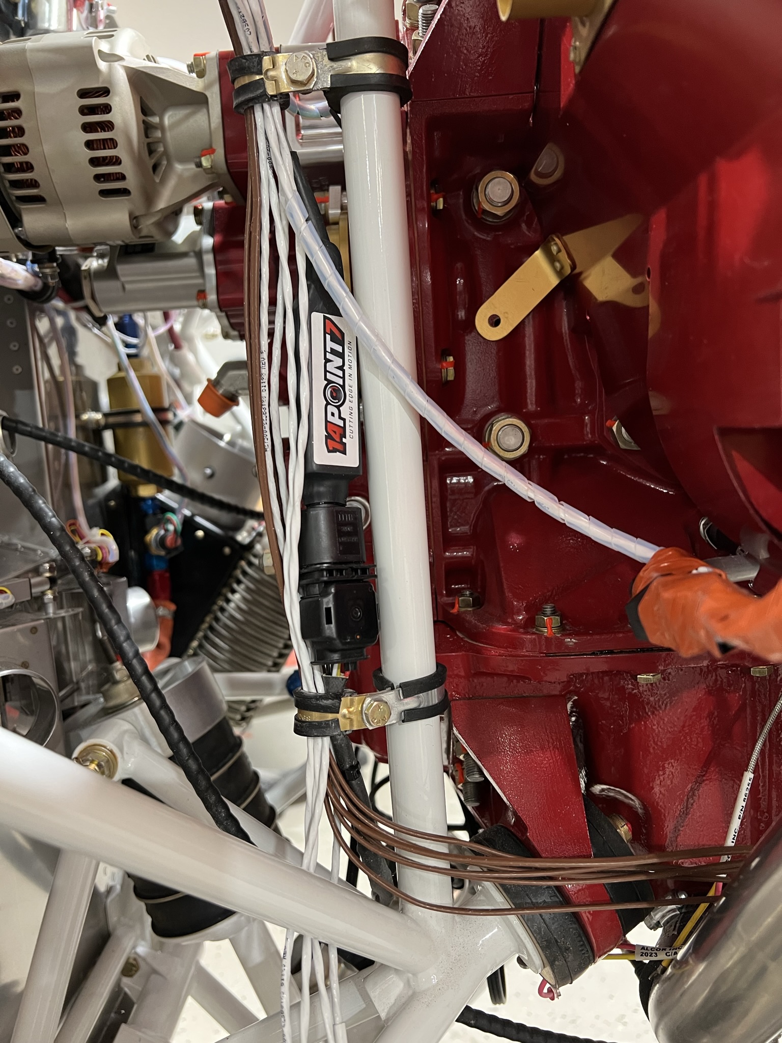
The 14Point7 Lamda 2 wideband controller was mounted on a vertical engine mount tube using adel clamps. Wiring is per the installation instructions. Note that it is the GREEN wire that connects to the GRAY ECU wire.
SDS uses Weather Pack connectors for all the FWF sensors / connections. For those unfamiliar with Weatherpack connectors , here is a link to one of the bazillion Youtube videos showing how this work. Crimping Weatherpack Connectors
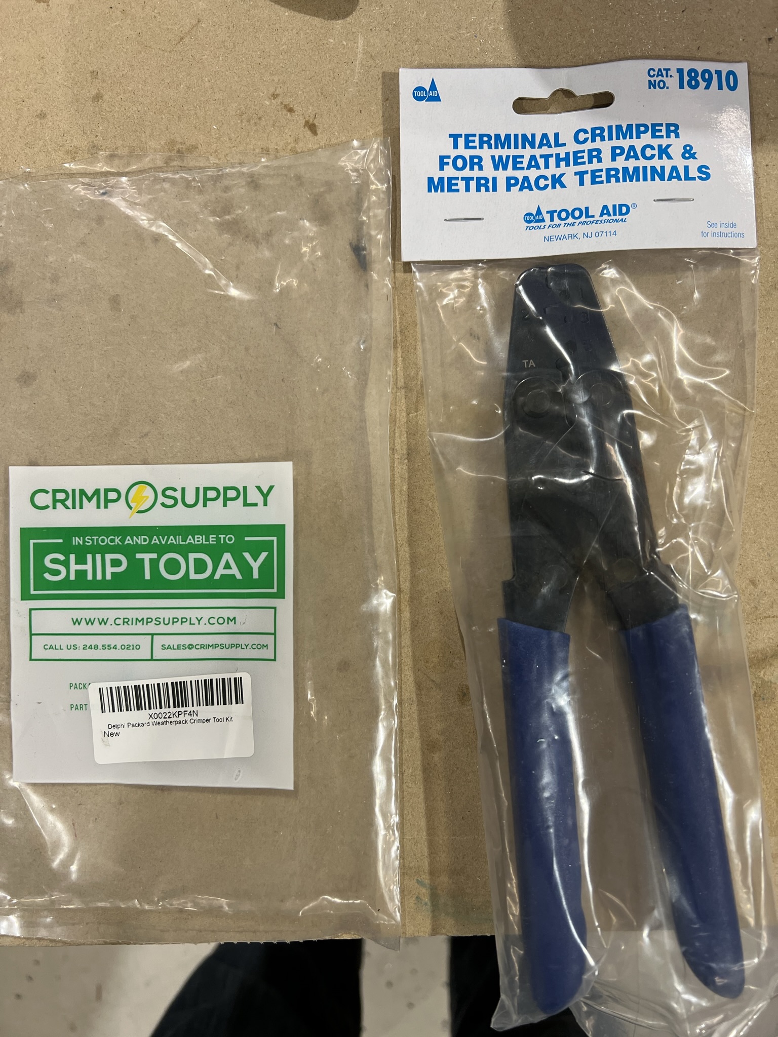
Here is the crimper I used. It is very inexpensive and is available on Amazon. I achieved very good results with it.