As a first step, be sure you have the latest installation instructions from SDS. They may have been changed since this was written so be sure to ALWAYS follow the SDS instructions. This webpage is only for informational purposes and shows how I approached the install. If there is a conflict between these pages and the SDS documentation, the SDS documentation governs.
The documentation I used can be found on the SDS Docs Page. The documents I used are listed below. I have not provided links, however, as I do not want to risk linking to stale documents.
The documents are
- EM-5 Aero Installation/ Tuning
- EM-5 Ignition Manual Lycoming
- Aviation ECU DB pinouts
- Dual 6 cylinder supplement/ wiring
Read all of these documents carefully before starting. Note that some of the documents provided directions for 4 and 6 cylinder configurations. Be sure to understand which is which.
As a first step, I suggest you examine the SDS wiring harness carefully and understand what goes where. In particular, there are a number of connections that are made using flying wires coming from the ECU DSub and Molex connectors. You will see that some such as the CHT / OAT / COIL / TPS / Hall Sensor leads go through the firewall to the engine., Others such as the KNOB leads are used near the panel. Understand which is which.
When installing the avionics hardware, there are a few things to consider:
- Where the ECU box will be located
- Where the relay box will be located
- Where the mixture know will be located
- where the know relay box will be locate
- How the wires to the engine will be run
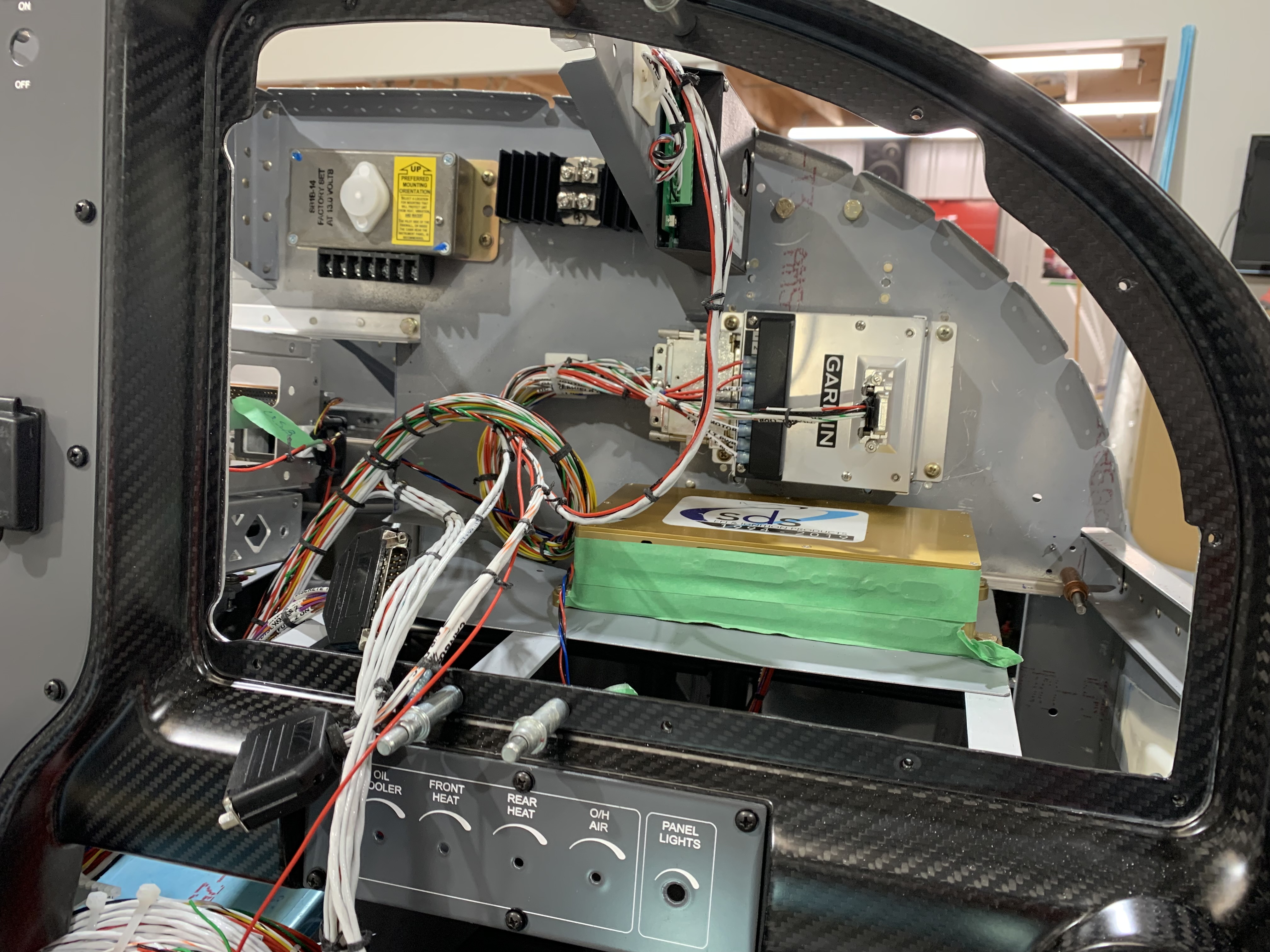
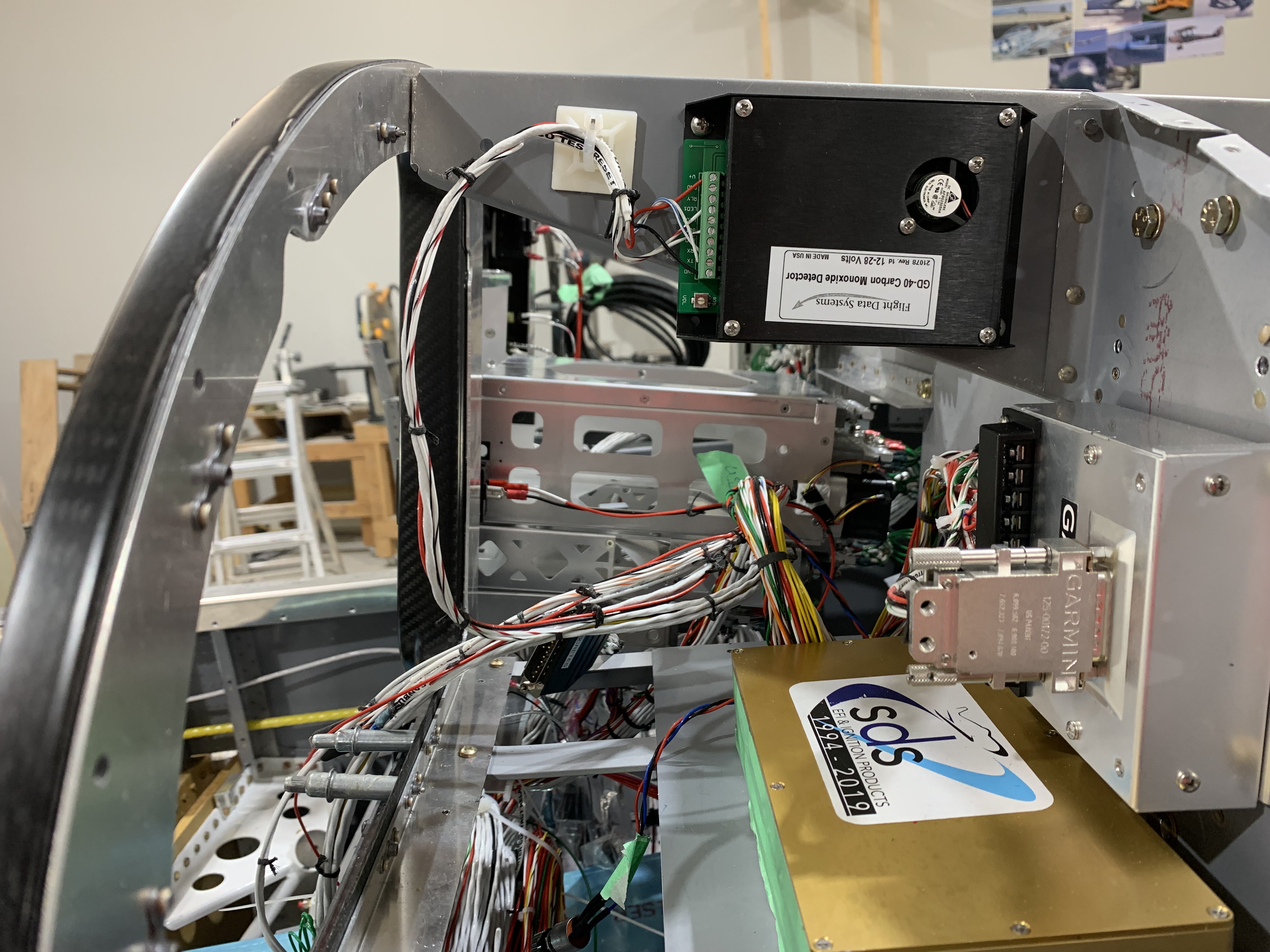
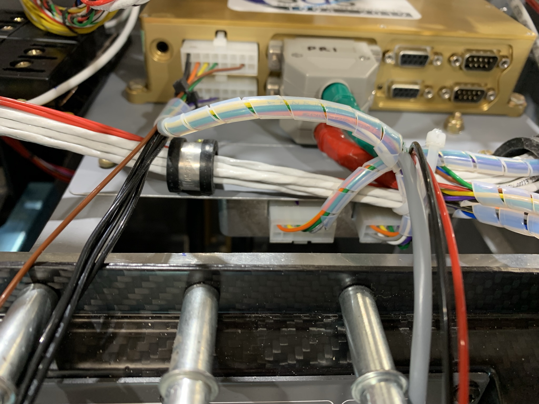
You will likely start with the installation of the SDS ECU (Engine Control Unit). The gold box should be mounted where it can be easily accessed in the event there are software updates. You can also install a small RCA jack that will allow access to the data logging features if you have purchased that option.
As the picture below shows, I mounted my ECU on the starboard side of the panel and used Adel clamps to hold the wiring harness securely in place. It is import
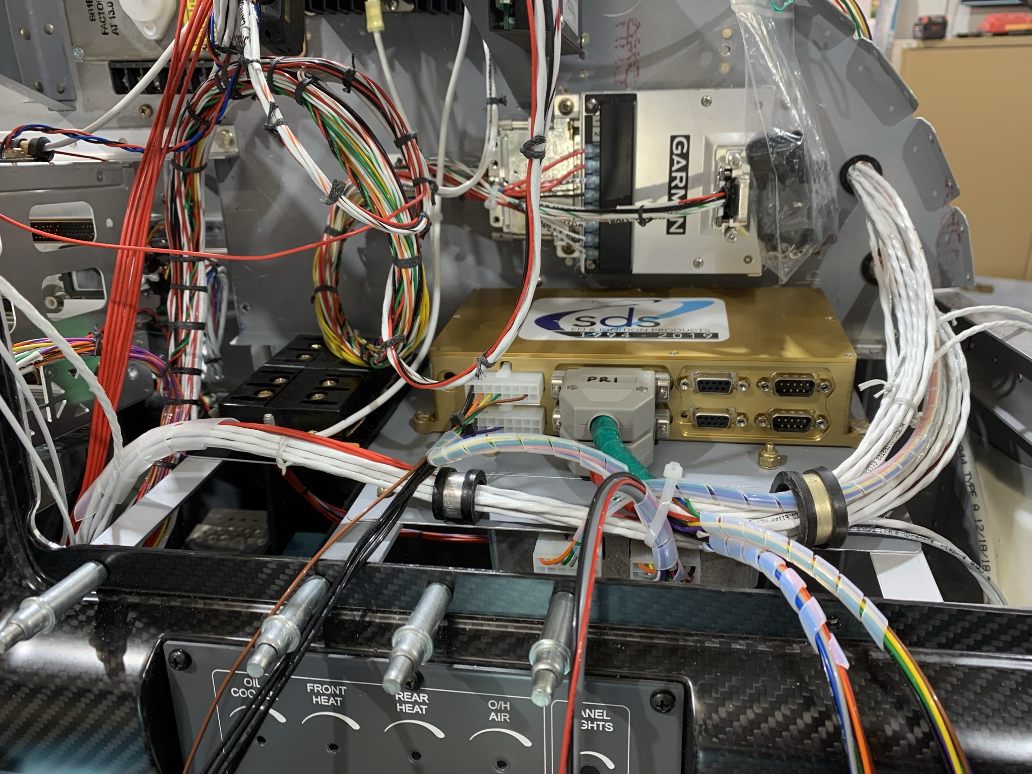
The ECU box, although a single unit, actually contains two ECCU computers that are electrically independent. The PRImary ECU is on the top, the BAKup ECU is on the bottom. Each has its own set of connectors.
I mounted the grey injector relay box under the the tray upon which the ECU sits. On the 3rd pix you can see the 4 screws that hold the box in place.
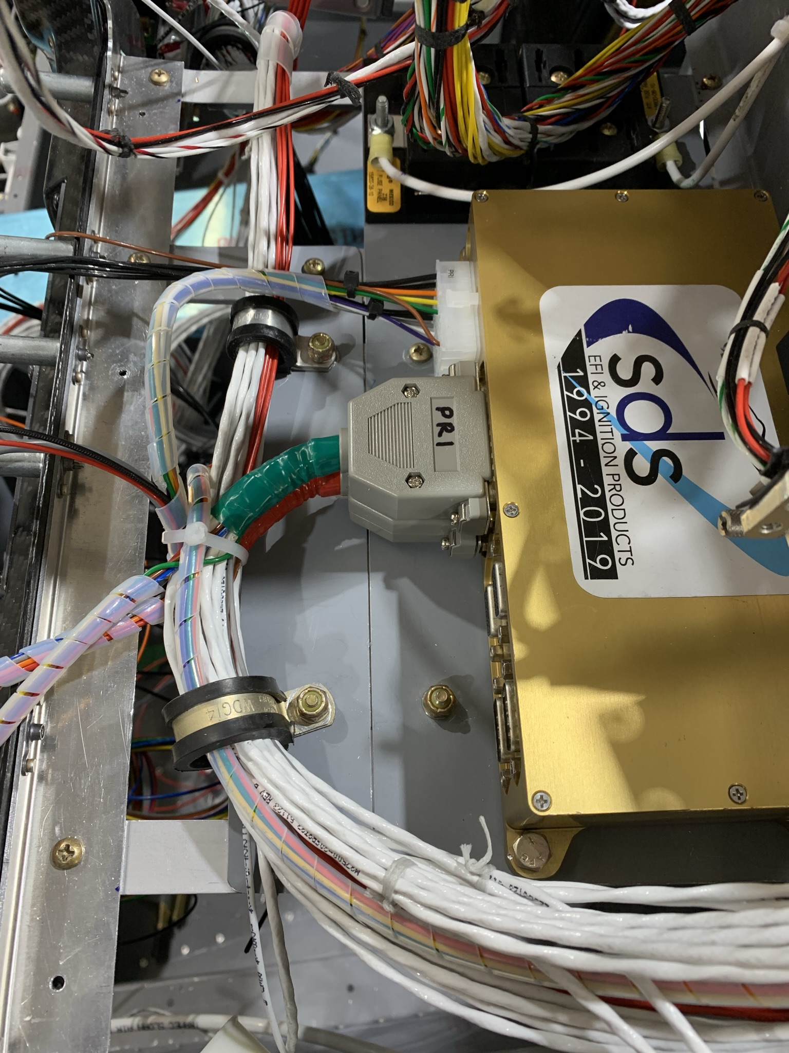
The first two pix shows the relay box below the tray as well as the wiring that goes into it. Later, when you install the mixture know, there will be two wires (brown and blue) that go from the knob harness into the RIGHT relay box Molex connector so be sure you can access it. The knob harness is also shown. There are three open Molex connectors on the end. The PRImary and BAKup connectors are mated to connectors you will install ion the KNOB leads coming from each of the 25 DSub pins on the PRImary and BAKup ECU
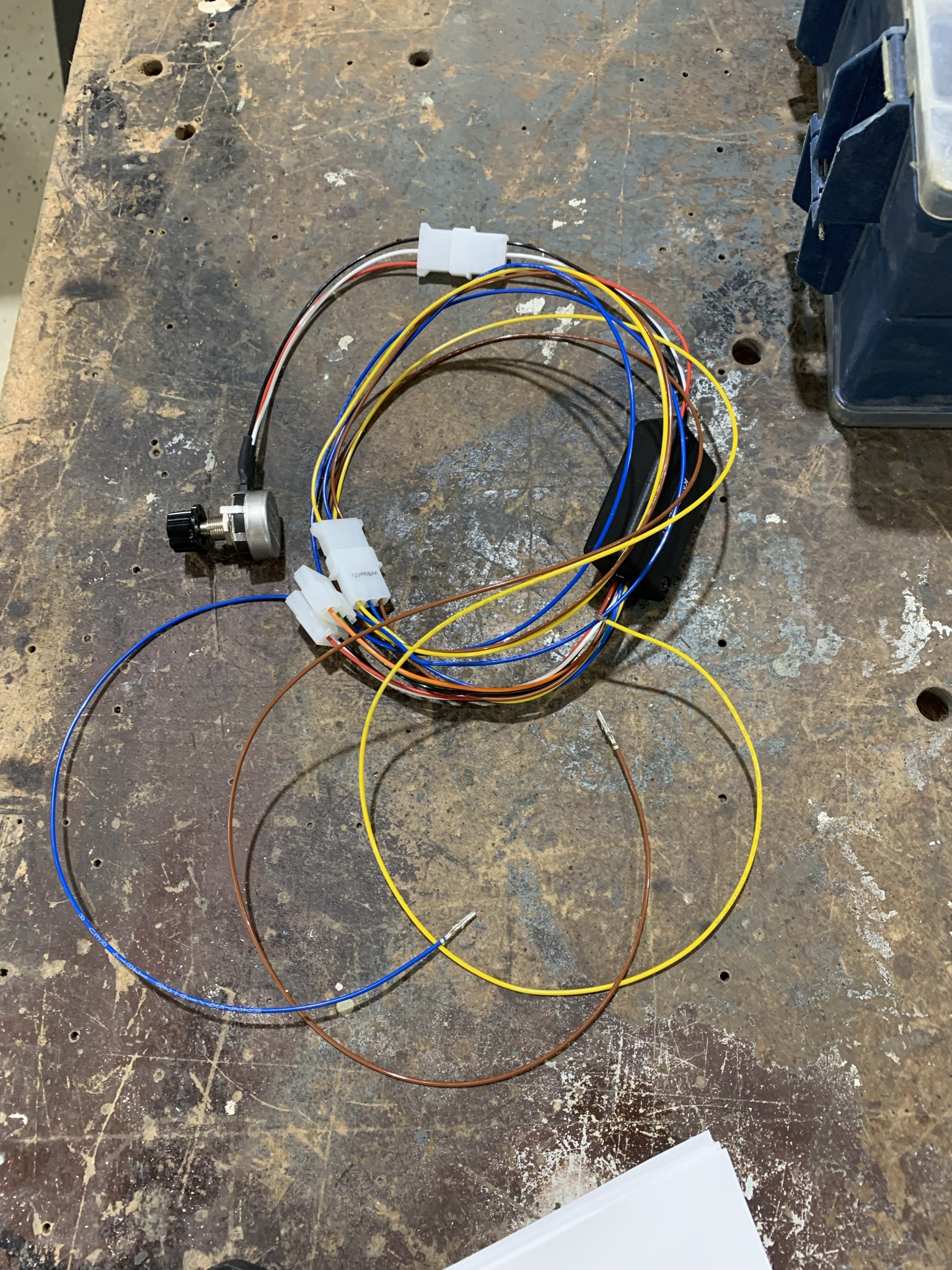
The SDS document : Dual 6 cylinder supplement/ wiring provides details of how to properly wire the KNOB harness.
When wiring the KNOB leads to the KNOB harness the following colour coding is used:
On the leads (from the ECUs):
On The Knob PRImary Molex
- White Signal
- Red Power
- Black Ground
On The Knob BAKup Molex
- Green Signal
- Orange Power
- Black Ground
On the 12VPRIBAK Molex
- Yellow To 12V power (be sure it is fused -1A is sufficient)
- Blue To RIGHT injector relay box Molex Pin 7
- Brown To RIGHT injector relay box Molex Pin 8
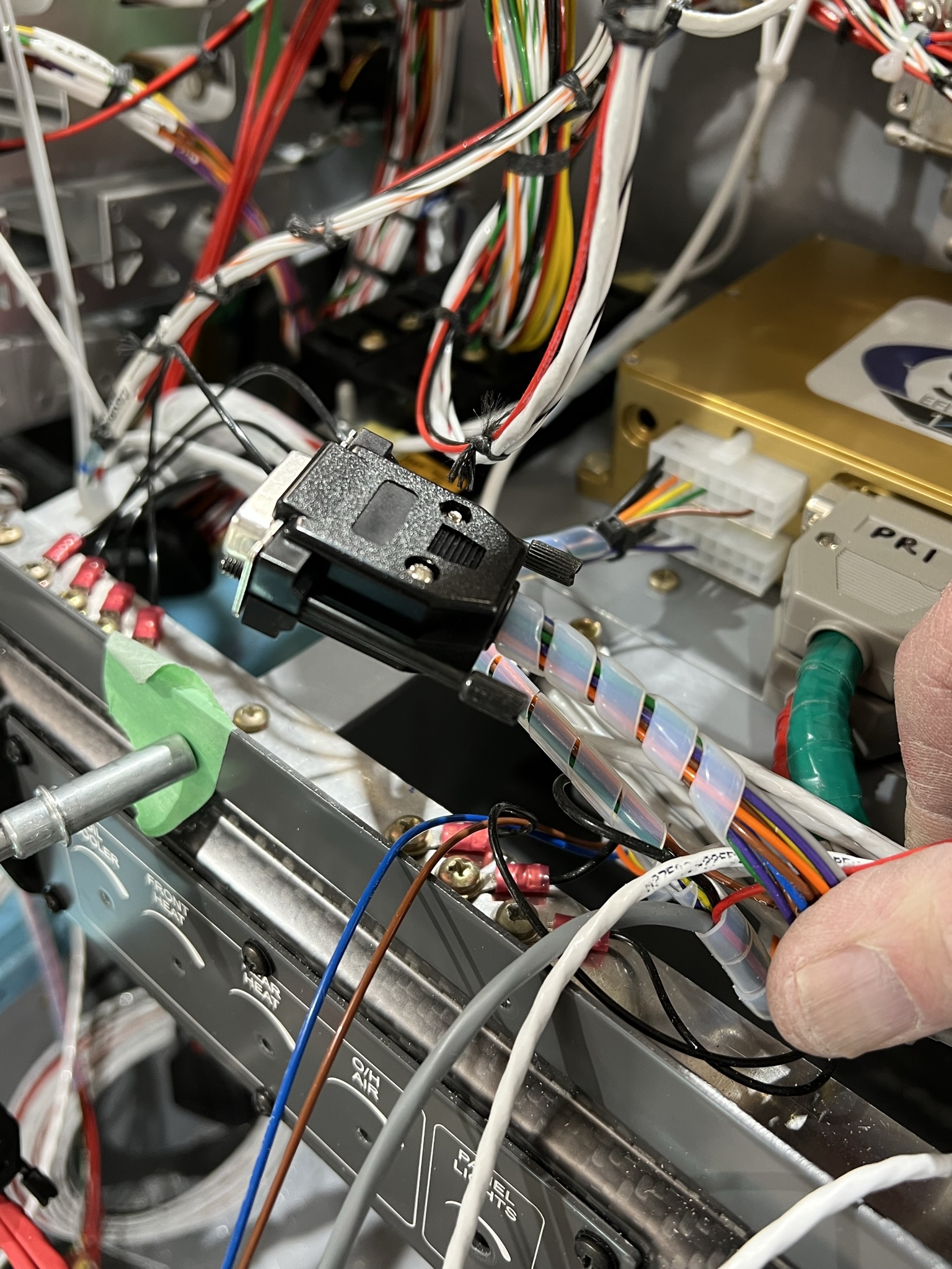
The first pix to the right shows how I removed the three Molex connectors and used a 9 pin D-DSub connector to make all the connections from the relay box to the injector relay box.
There is a 25 pin D-Sub connector attached to each ECU. There are a number of shielded multi wire leads coming off the D-Subs as well as a number of individual wires. The shielded multi wire leads are individually labelled. They connected to the various engine sensors (TPS / Air Temp / Engine Temp / Manifold Pressure / Coils). The colour coding convention used by SDS is as follows.
- White Signal
- Orange / White Power
- Blue / White Ground
- Shield Not used
The individual wires are documented in the SDS instructions, which is reproduced below:
- Blue Optional Lean of Peak Switch (only used on PRImary ECU)
- Red 12V power to ECU
- Black ECU airframe ground
- Gray O2 Sensor input (only used on PRImary ECU if O2 Sensor installed)
- Green Tach Output 5V
- Yellow Tach Output 12V
- Purple Do not use – for future use (not shown in SDS graphical documentation, in text)
- Brown Do not use – for future use (not shown in SDS graphical documentation, in text)
- Orange Only on BAKup ECU, it is connected to the White Signal wire in shield TPS multiwire lead
Only the Gray O2 Sensor wire on the PRImary ECU is used and only if an O2 sensor is installed.
The Blue wire is only used if you are using a Lean of Peak switch rather than using the button on the SDS controller. You can only use one or the other.
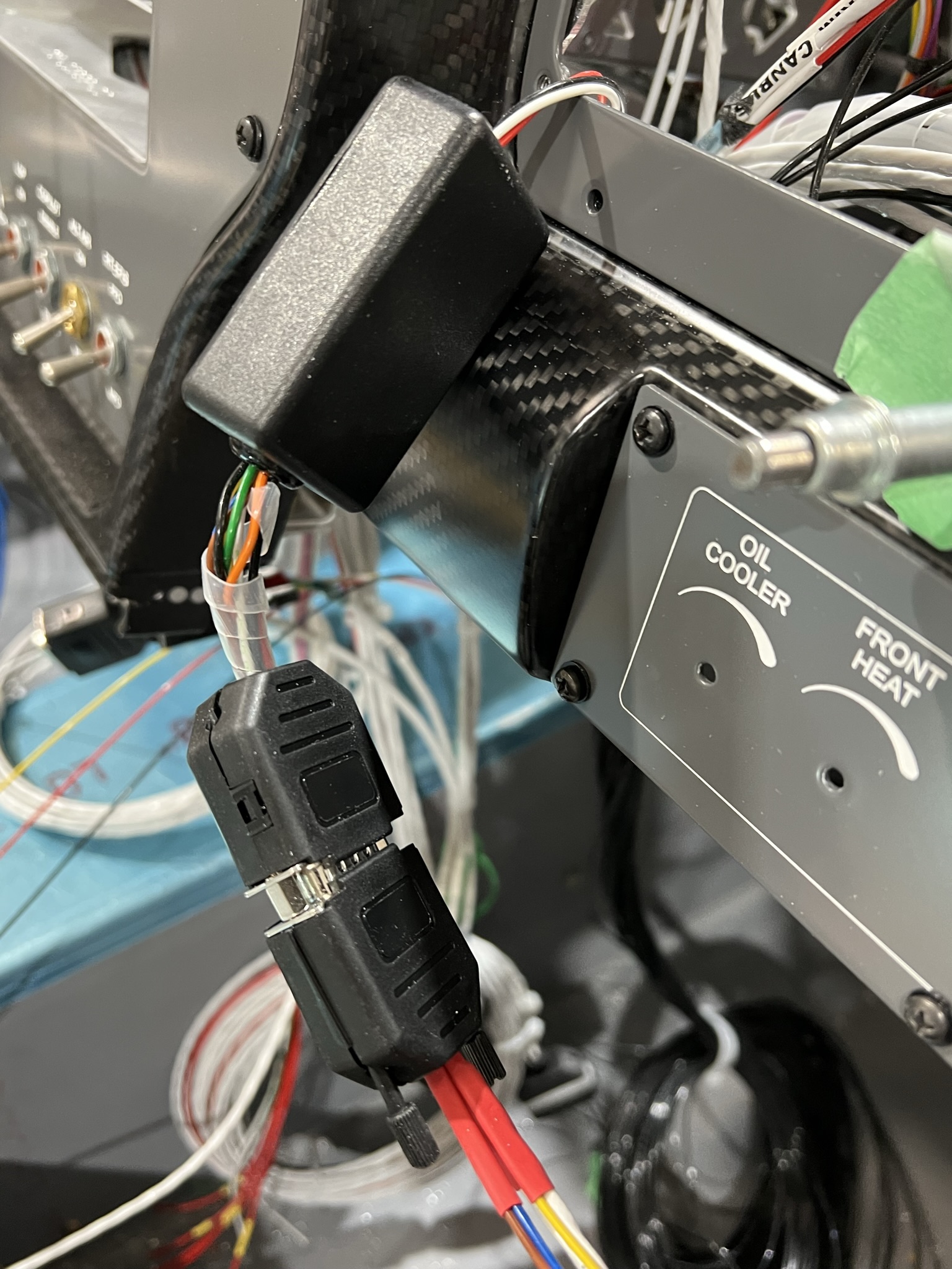
The pix on the right shows how I used a 15 pin D-sub connector to handle all the flying leads, other than power and ground coming off the PRImary and BAKup 25 pin ECU connectors. Coming from each of these connectors is a Purple and Brown lead. None are used at the moment : the Purple & Brown) are added for use with future ECU upgrades. The Blue wire is used if you are using a LOP (Lean of Peak) switch. The new controller heads have this built in so it is not needed unless you want to use a dedicated LOP switch. As these three leads are abandoned in place, it seemed to make sense to use a D-Sub so connections in the future would be easier to make.
You will also see a Brown wire coming from the molex connectors on the left side of the left side of the ECU box. This wire provides a signal to that your ECU can use to determine instantaneous fuel flow. Using this signal, which is derived from when the fuel injectors are open, eliminates the need for a “red cube” fuel flow transducer. For ease of making the connection to the Garmin G3X EFIS, I also added this wire to the 15 pin DSub connector noted above.
Be sure to confirm these with your install.
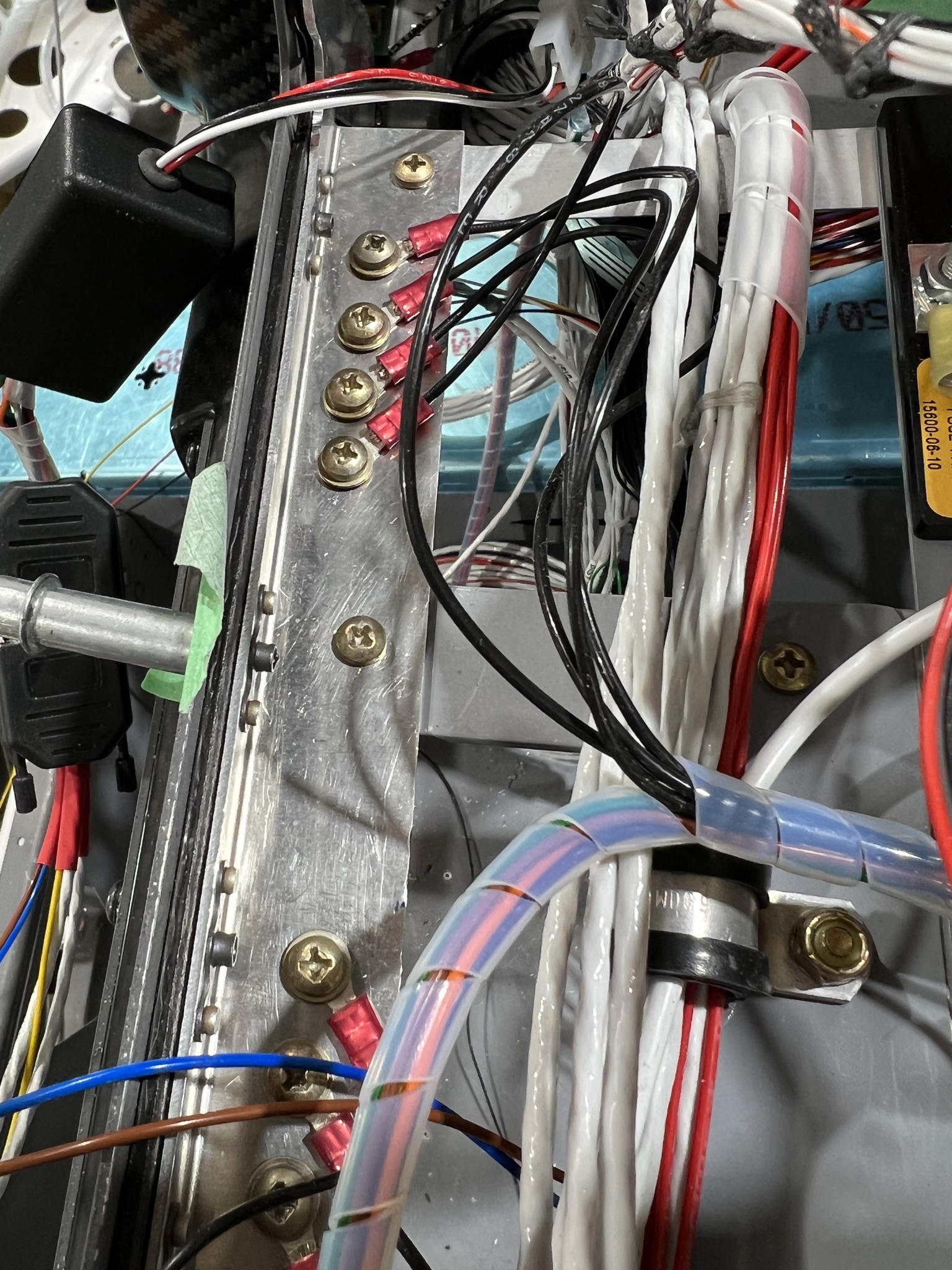
You will notice that there are several black ground wires coming of the ECU and relay box harnesses. These grounds do not have to go to the main firewall ground block if good local grounds are used. In fact, it is desirable to ground these close to the ECU. It is essential, however, that these grounds be separate as in some cases they are redundant grounds. It would be catastrophic if a single point servicing multiple grounds failed and caused an ECU failure. Redeundancy is your friend! Follow the SDS recommendations and use separate grounds as shown in the pix to the right.
Along with the grounds there are multiple power leads (RED) that must also be connected. Be sure to fuse these as recommended by SDS. There are separate power wires for the ECUs (PRImary & BAKup) and the injector relay box. Other power wires will be discussed later.
Again, and I cannot stress this enough, be sure to fuse your system correctly. A loss of power to any one of the SDS components could result in an engine failure. So check your wiring, grounds and fusing, double check it and then when you are sure it is correct : CHECK IT AGAIN!