Caution to reader:
This document is specific to dual ECU, 6 cylinder installations. While many of the concepts are the same in 4 cylinder installations, operating and installation requirements are quite different. All operators must follow SDSEFI instructions applicable to their systems.
This document does not amend, over-ride or supersede SDSEFI documentation. In the event of a conflict, SDSEFI documentation takes precedence.
Understanding how the SDS EFI/EI system controls the IO-540 engine is essential for effective engine operation.
This document outlines key concepts that you must understand.
Engine Control Unit (ECU)
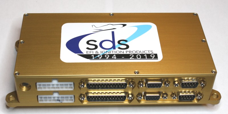
The SDSEFI systems uses dual (two) ECUs to control engine operation. Each ECU is a specialized computer that determines how the engine ignition and fuel injection systems operate. Although only a single ECU is required to run the engine, optimal performance requires dual ECU operation. Typical these ECUs are referred to as the Primary or Secondary ECU.
The gold box contains tghe two ECUs which are electrically independent (notice the duplicate set of connectors on the back of the unit. The only connections between the ECUs is a single wire which determines which ECU(s) are controlling the engine (primary / secondary or both) as well as shared input from the Throttle Position Sensor (TPS).
Sensor Suite
The SDSEFI system employs a suite of engine sensors, these being:
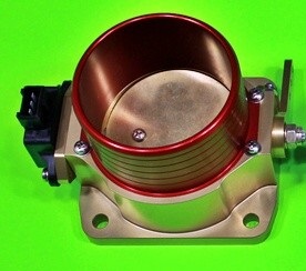
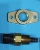
Throttle position sensor (TPS) : this sensor is shared by both ECUs. Located on the throttle body It reports the throttle body position. The pix shows the red/gold throttle body as well as the black sensor mounted on the left.
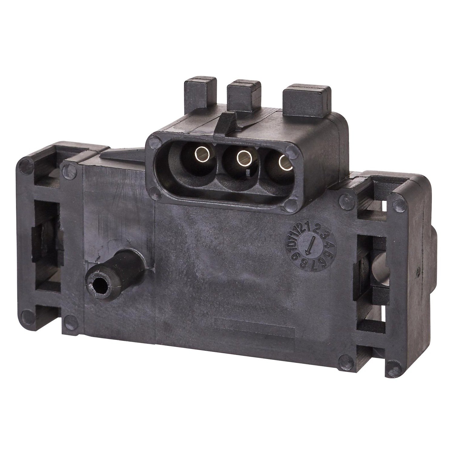
Manifold pressure sensor (MPS) : a sensor is supplied for each ECU and reports manifold pressure measured at the base of the throttle body. A 3/32 hose connects the port on the front to hose barbs mounted at the base of the throttle body.
Parenthetically, a third MPS may also be required as an input to your EFIS Engine Monitoring System. If so, simply use a brass hose barb “T” on one of the hose lines from the TPS.
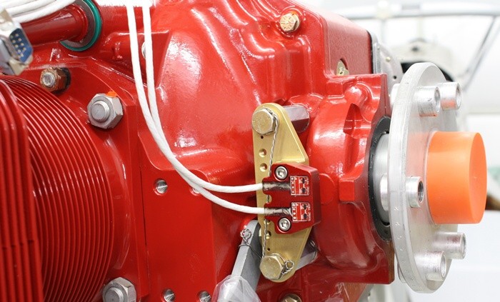
Hall Sensor (crank position) : this sensor module, which is located behind the flywheel, has two pickups which measure the position of the engine crank based on magnets embedded in the flywheel. One pick is dedicated to each ECU. The magnet position values, different for each pickup, are recorded in the respective ECU. Note: SDS no longer requires engines to be timed using a timing light as all flywheels now have factory installed timing magnets. Users should use SDSEFI supplied values for magnet positions when programming ECUs.
IAT (intake air temperature) sensors : a sensor is supplied for each ECU. Typically these sensors are mounted on the engine induction air system prior to the throttle body. However, these sensors can be mounted anywhere that see’s induction air temperature including on the throttle body, in the Filtered Air box, and even on the baffles where inlet air temperature can be measured. The gold mounting boss is also shown.
Engine temperature sensors which are used for stating and warm up.
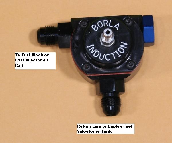
Borla fuel pressure regulator : this controls / regulates the fuel pressure “seen” by the engine side of the fuel system.
ECU Programming
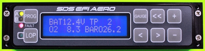
The ECUs are programmed using the “Prog” button on the “Programmer” typically installed on the instrument panel. This module is only an interface to the ECUs and is not used to control the ECUs beyond providing entry of programming values and initiating Lean of Peak (LOP) operation.
Each ECU contains a “map” of values which is used by the ECU to determine fuel flows and ignition timing for various combinations for engine temperature, outside air temperature, manifold pressure and engine RPM.
With a few specific exceptions, the ECUs must contain exactly the same values for all entries. Entries that have different values are:
- Magnet position for the primary crank sensor (stored in the Primary ECU)
- Magnet position for the secondary crank sensor (stored in the Secondary ECU)
- Fuel trim values for cylinders # 1, 2 & 3 (stored in the Primary ECU)
- Fuel trim values for cylinders # 4, 5 & 6 (stored in the Secondary ECU)
- Spark advance and fuel adjustment when LOP is active (stored in the Primary ECU).
Trim Values
Trim values are the +/-% fuel values applied to individual cylinders. These values, which typically do not change once set, allow balancing of fuel flows to each cylinder so that all cylinders reach peak EGT at the same time. This balancing is required to allow efficient and smooth Lean of Peak operation.
In engines with traditional mechanical fuel injection, balancing was a trial and error process that required swapping injector nozzles between flights. The SDS system eliminates this hardware change by allowing % fuel values (trim values) to be adjusted inflight using the programming controller. Consequently fuel flow balancing of cylinders is easily and quickly accomplished.
ECU Select Switch (Primary / Both / Secondary)
This switch controls which ECU(s) control the fuel injectors. It does not control which ECU is controlling the engine ignition.
In the Both position, the Primary ECU controls the injectors for cylinders #1, 2 & 3. The Secondary ECU controls cylinders # 4, 5 & 6.
When either the Primary or Secondary ECU is selected (not Both), the selected ECU controls all 6 injectors. Special features (Lean of Peak switch etc.) are, however, disabled. The change in engine operation, especially at low power settings, will be barely noticeable if at all. This is because all plugs still fire and the only change is in which ECU is controlling the injectors.
You may notice a change if the cylinder trim values are markedly different between cylinders # 1, 2 & 3 and cylinders # 4, 5 & 6. This is because the trim values for the cylinders otherwise controlled by the now unused ECU are replaced with the values of the in use ECU. For example, if the Primary ECU is selected, then the trim values used for cylinders #4, 5 & 6 are the values assigned the same values found in the Primary ECU for cylinders # 1, 2 & 3. If trim values are not specified or small, then there will be no noticeable change when either ECU is selected.
Coil Packs
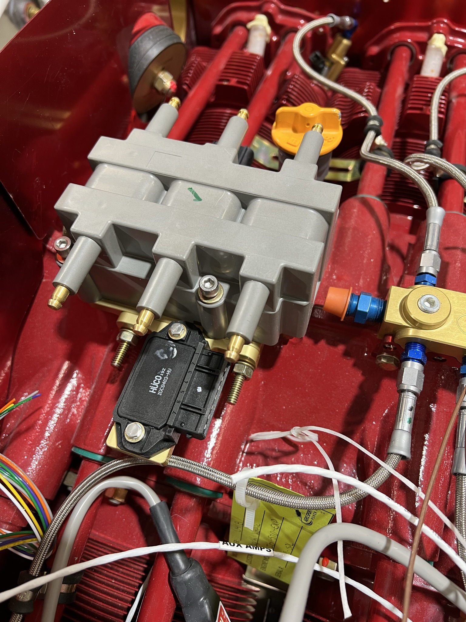
The SDSEFI system uses two coil packs (analogous to magnetos).
Coil pack # 1 normally controls the top 6 engine spark plugs.
Coil pack # 2 normally controls the bottom 6 engine spark plugs.
Turning either of the coil packs off has the equivalent effect of a mag check; you will see a 75-100 rpm drop as one set of the engine spark plugs is turned off.
Each coil pack is controlled by one ECU; the Primary ECU normally controls the top spark plugs, the Secondary ECU normally controls the bottom spark plugs.
Each coil pack contains three coils each of which fires a spark plug in each of two cylinders at the same time. As the firing occurs when only one of the cylinders has compressed fuel, the spark to the other cylinder (which is in an exhaust stroke) is wasted.
Fuel Flow Measurement
In mechanically injected engines a “Red Cube” fuel flow transducer is used to measure actual fuel flow. In an EFI system, unused fuel is returned to the originating fuel tank. To measure fuel with a flow transducer, a transducer must be mounted before and after the engine. The difference in the measured signals is the fuel consumed.
If desired, the SDS system can provide digital fuel flow information to EFIS systems. The digital signal is based on how often the electronic injectors open. It important to realize that actual fuel flow is not being measured. Therefore, if fuel to the injectors is restricted (say because a fuel filter is blocked), the fuel flow may be overstated.
Normal Operation
In normal operation, the ECU Select switch is set to Both and both coil packs are turned on. In this case the ECU special features (LOP operation & trim values) are active.
Run-Up Tests
Typically a pre-flight run up will involve the following steps:
- Open throttle to 2,100 RPM
- Select fuel pump # 1 then fuel pump # 2. There should be no change in fuel pressure or engine operation. There should be no drop in RPM.
- Switch from Both ECUs to Primary ECU to Both ECUs to Secondary ECU to Both ECUs. There should be no noticeable change in engine running (unless trim values are markedly different between cylinders – see note above.
- Switch coil pack # 1 off. There should be a normal rpm drop (75-100 RPM) similar to a mag drop. Switch coil pack # 1 on and turn coil pack # 2 off. Again there should be a 75-100 RPM drop.
Failure Modes
Whenever an engine problem is suspected, it is essential that the backup fuel pump be turned on immediately if not already on.
ECU Failure
Of the 2,000+ ECUs supplied by SDS, there has been only one confirmed failure. That being said, an ECU failure is easily diagnosed and handled in flight.
When in the Both configuration, a failure of either the primary or secondary ECU will result in a very rough engine as the cylinders on either side of the engine will be dead. If this happens immediately switch from Both to Primary ECU. If the problem persists (or the engine stops), switch to the Secondary ECU. This will isolate the bad ECU and allow safe flight to the nearest airport.
Blocked Fuel Filter
A blocked fuel filter can manifest itself in a few ways
- Higher than expected CHT values even when the fuel flow appears nominal
- Current draw is higher than expected (due to electric fuel pumps working harder)
- Erratic fuel pressure values
- Higher than normal fuel pressure IF the fuel pressor sensor is installed before a firewall mounted fuel filter. This will, however, only help detect a blockage in the firewall mounted filter.
If a blocked fuel filter is suspected, immediately switch fuel tanks and land as soon as possible. All fuel filters should be removed / inspected / cleaned or replaced as appropriate before future flight.