The main SDS harness can seem quite daunting. However, in reality it is quite simple. It consists of a number of multi-conductor and single conductor wires. This section will focus on the wires that pass through the firewall.
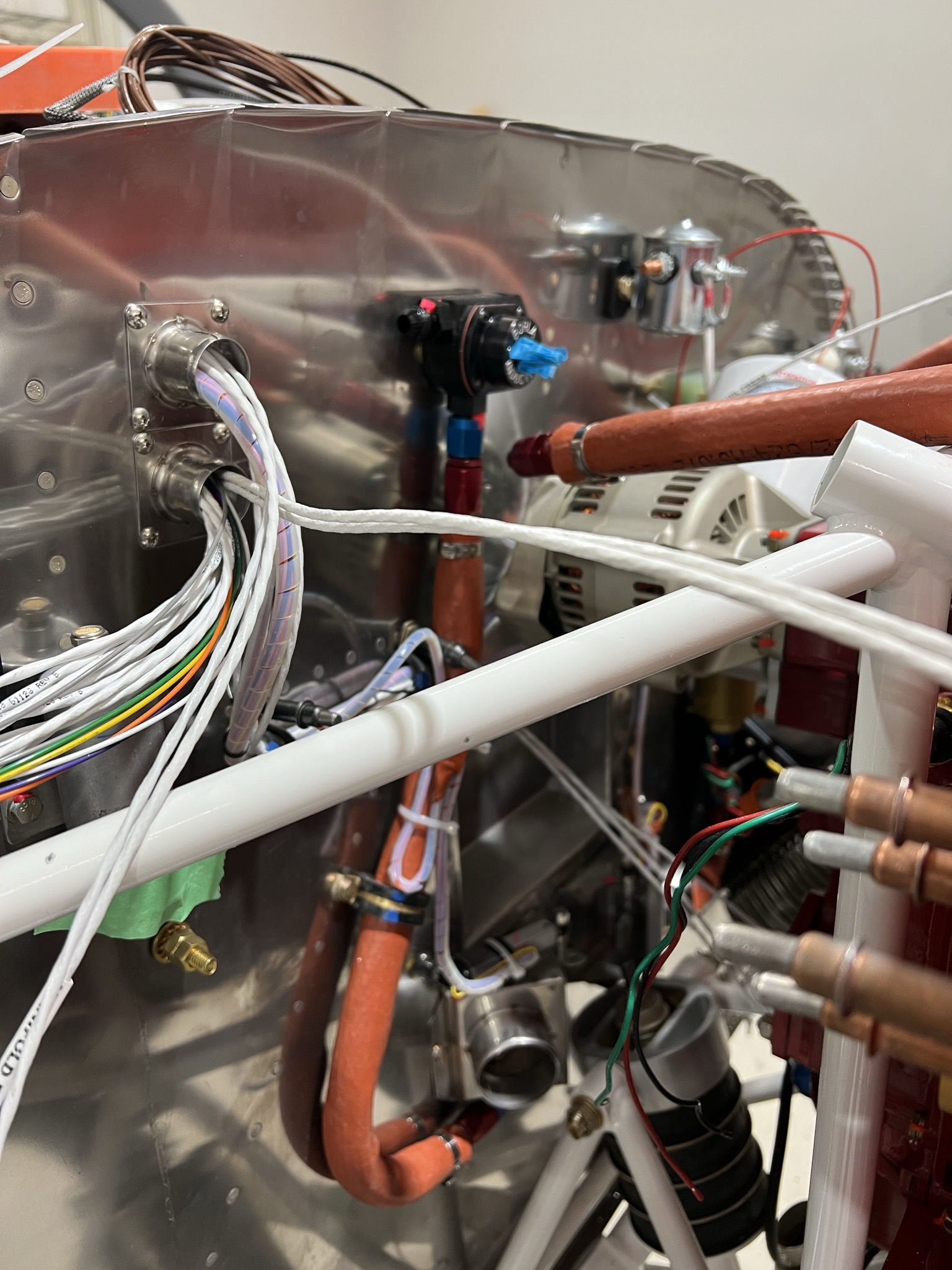
Although it is possible to squeeze all the FWF wires through a single passthrough, I have used two passthroughs. One for the SDS wiring and another for the Garmin G3X sensors as well as the TCW servo wires, alternator fields, etc.
I used 2 of the 3/4″ firewall stainless steel penetrations available from Aircraftspruce.
You will note that in most cases there are 2 of each type of wire as there are two ECUs. Each ECU (with one exception) has its own sensor suite.
The SDS wires that come FWF are:
2 Outside temperature probe multi conductor wires
2 Hall sensor multi conductor wires
2 Coil trigger multi conductor wires
2 CHT multi conductor wires
2 Manifold Pressure Sensor (MPS) multi conductor wires
1 set of injector power leads (6 wires)
1 set of injector ground leads (6 wires)
1 Throttle Position Sensor (TPS) multi conductor wire
Note that the signal from the single TPS is shared by each ECU. I jumpered this signal at the ECU rather than FWF.
If you examine the ends of the multi conductor wires you will see that they are marked in indelible ink as CHT, AT, TPS, COIL, MPS. I suggest you use tape to make these wires in case the ink wears off. You don’t want to be guessing what each wire is.
In those cases where connectors need to be attached to various wires, you will find small plastic bags containing each of the connectors.
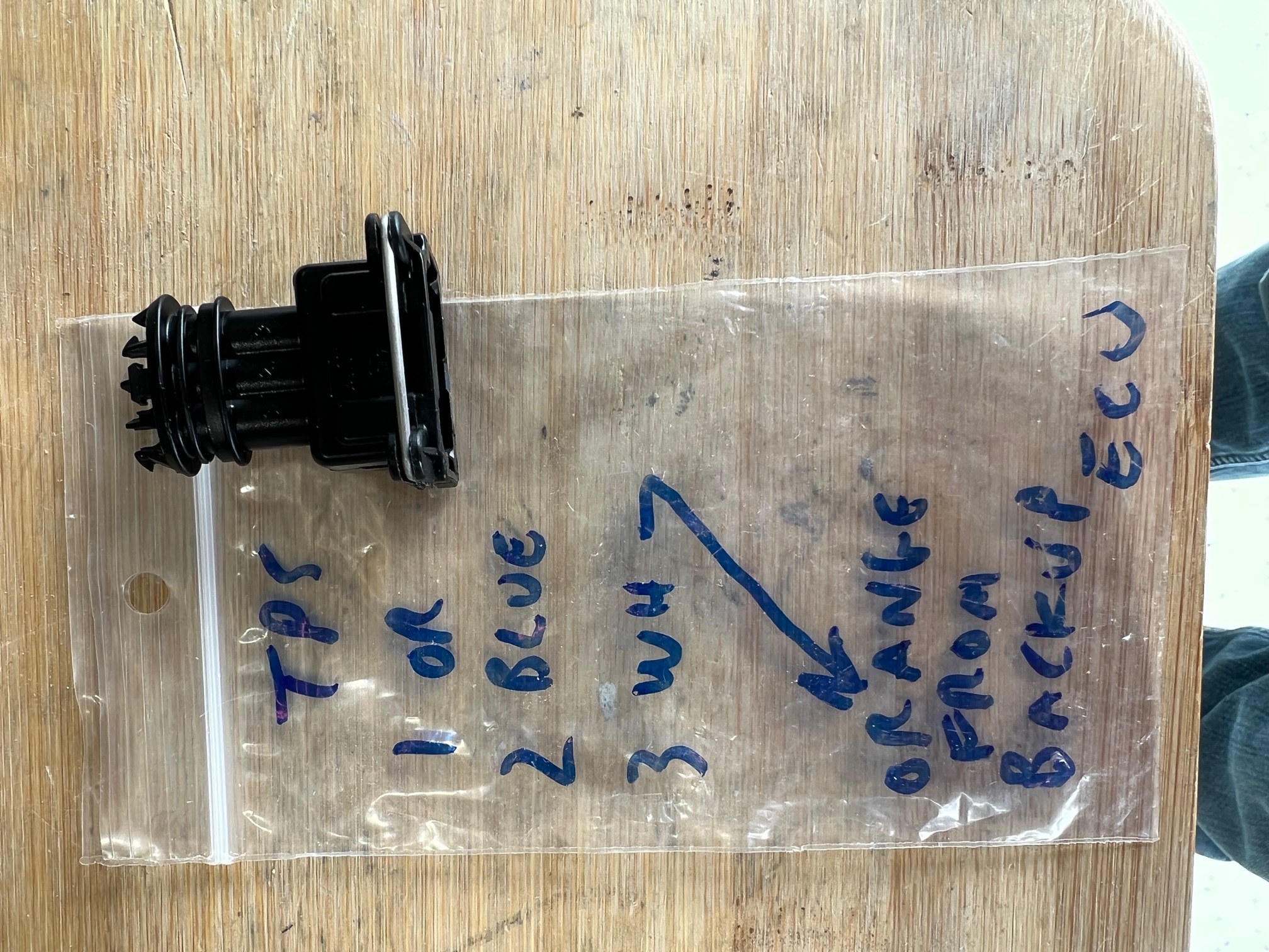
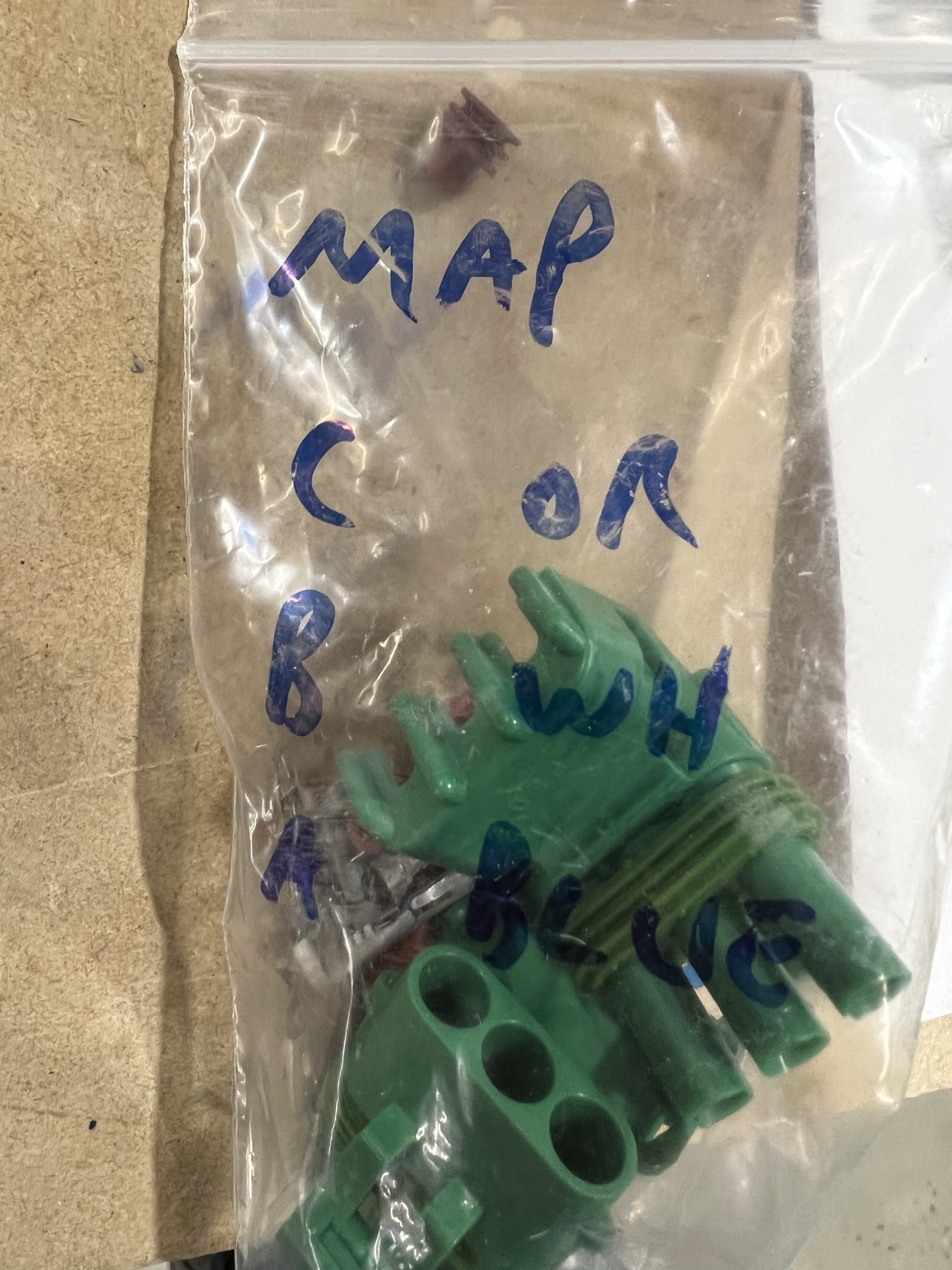
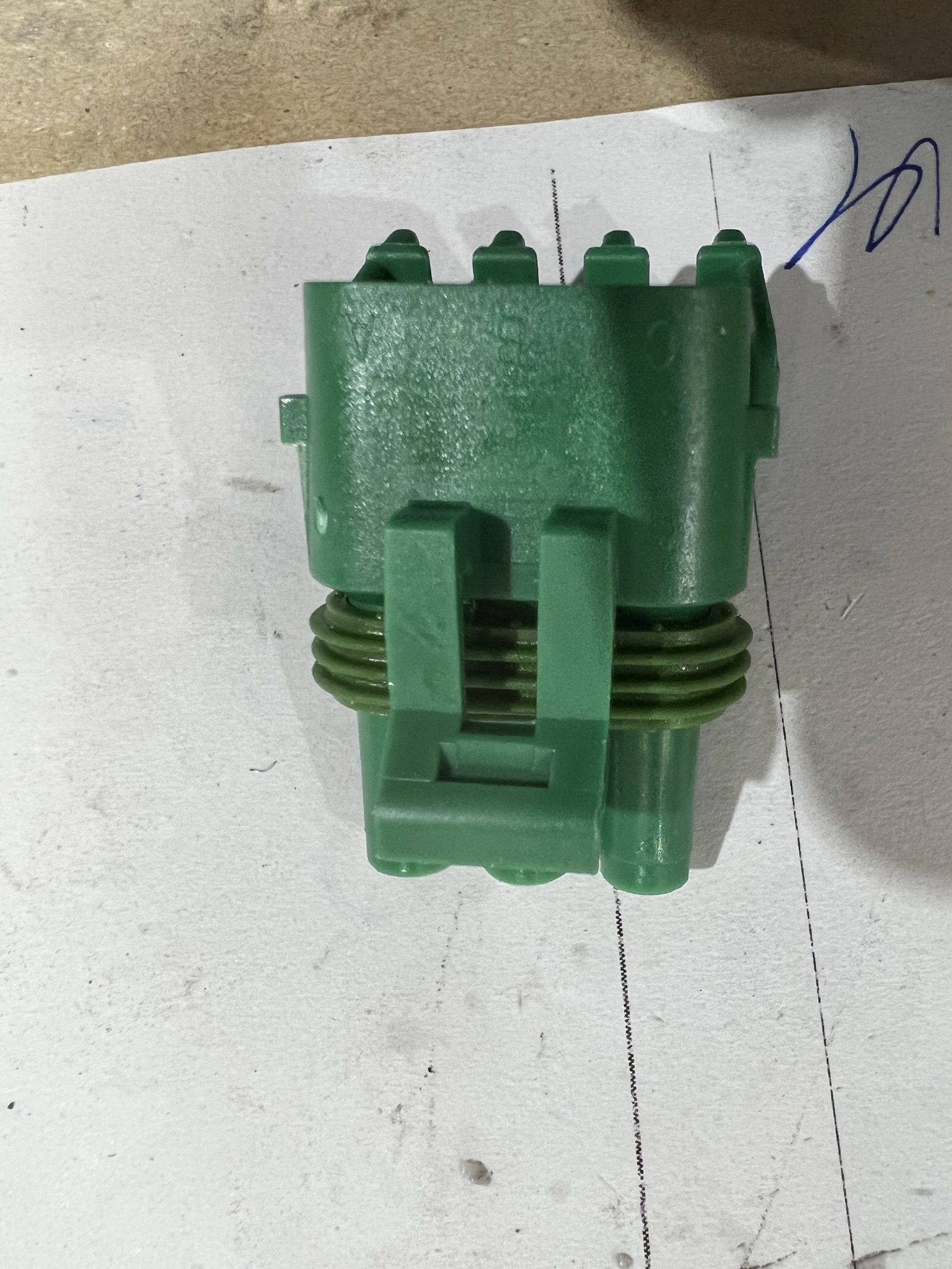
The pix above, for example show the connector that attaches to the throttle body. You will note that the bag indicates which colour wire connects to which pin position (1,2 or 3). You will also see the pin positions marked on the connector. Match the right pin to the right connector position.
Some of the other sensors (CHT / OAT etc) use WeatherPak connectors. For these connectors, the connectors are labelled using letters (A,B,C, D etc). The plastic bags are marked accordingly. Look at the connectors carefully as the lettering may be difficult to see.
SPECIAL NOTE
The two hall sensor multi conductor wires come with 9 pin D-Sub connectors soldered to each. If you remove the backshell, these connectors will go through the firewall penetrations if installed first. Alternatively, you can remove the connectors and reinstall new connectors at a later time.
If you choose to keep these connectors on, see the page on the Hall Sensor Install to see how the transition through the rear baffles was accomplished.