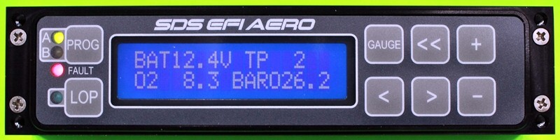
The MAPS used by the SDSEFI/EI system, are used by the Engine Control Unit(s) (ECUs) to control how the engine operates. The ECU controls how the engine runs. The MAP contains parameters used by the ECU in its operation. The MAP parameters are entered using the PROGRAMMER shown above.
Below I will walk through the MAP used to control my Lycoming IO-540 engine with 9:1 compression pistons, Barret cold air induction. As always, the info below represents what I use and explains the rationale used in determining various values. When looking at the MAP, the values in green or yellow represent values changed after engine break-in.
You may not need to change any SDS supplied MAP values during engine break-in. Once break-in is complete, you may adjust the MAP as required to achieve optimal engine performance. See the Engine Tuning page for details on how this may be accomplished.
Readers are cautioned that in all cases documentation contained on the SDSEFI.COM website always takes precedence over anything on this website. Readers use this information at their own risk. The MAP presented is what I use and may not be appropriate for your installation.
The MAP controls engine operation under various operating conditions. Note that the table contains values up to 4500 RPM. However, my IO-540 is governed never to exceed 2700 RPOM. Consequently these values above 2700 RPM are never used.
The base values used in my table were provided by SDS with my ECU in 2019. Since then SDS supplied base values may have changed. Please keep this in mind when reading below. Always consult with SDS if you are unsure as to what changes are to be made.
Readers are cautioned to never change low RPM / low manifold pressure values as these values are essential too keep the engine operating in low power situations. See the SDS Lycoming Tuning Guide for more details.
RPM/Fuel Factor
The first major element of my table controls fuel flow based on engine RPM. Your will see a FUEL FACTOR associated with each engine RPM value in 100 RPM increments. In each case the factor is 140 except for 2600 and 2700 RPM. In this case the factor becomes 231. The increase at high RPM reflects the need for additional fuel at high power settings. By increasing fuel using the MAP, there is typically no need to manually enriched the engine during take-off. The 140 fuel factor represents what is necessary during normal cruise operations.
I modified the values used when tuning my engine. However, during break-in, I manually increased mixture to control CHTs and to ensure the engine was receiving sufficient take-off fuel.
Manifold Pressure / Fuel Factor
These table entries adjust fuel flow based on the selected manifold pressure. You will notice that except for the first two entries, the fuel factor increases as manifold pressure increases. This is logical as higher manifold pressure increases require more fuel to make the increased power demand.
The first two entries in the this table typically only come into play when starting the engine. They provide a high amount of fuel to facilitate starting.
The factors used were not changed.
Start Temp / Fuel Factor
These table entries are usually only used to increase fuel to the engine when the engine is cold. You will note that as the temperature of the engine increases, the fuel adjustment tapers off. Once the engine is at normal operating temperatures (176F and above), the factor goes to zero.
The factors used were not changed.
RPM / Ignition Timing
This table determines the engine timing in degrees before top dead center (BTDC). At lower RPMs, the timing is reduced to allow better combustion of fuel – slower RPMs mean there is more time for fuel to burn so ignition can be delayed somewhat. At normal cruise RPMs (at or over 1500 RPM), the timing becomes 24 degrees BTDC which is the recommended value for my engine. It is what would be used if magnetos were installed.
IGN RET-ADV/LOAD
These factors allow ignition timing to be changed through the fuel range of Manifold Pressures. In my case I do not use these table entries. In my opinion, there is no need to use these values as my timing is optimally set when cruising at 2400 RPM regardless of what Manifold Pressure is being used / achieved. By setting these values to zero, engine tuning is simplified – particularly tuning for Lean of Peak (LOP) operations.
All values set to zero.
Air / Temp
The Air / Temperature factors adjust fuel based on the Outside Air Temperature (OAT) measured by the ECU OAT sensors. As air becomes colder, it’s becomes denser and therefore more fuel is required to maintain the desired Air/Fuel ratio.
No change was made to these values.
Other Single Entry Values
There are a number of other values that can be set using the SDS programmer. The values below represent the parameters that were available in my ECU as of 2019. Future changes to the ECUs will likely introduce new parameters not reflected below.
Always consult SDS documentation before changing any of these parameters. Incorrect parameters can cause serious problems.
Start Cycles: 32;
ACCUPUMP HIRPM: 20; Adjusts fuel flow when there is a dramatic increase in the manifold pressure
ACCUPUMP LOWRPM: 40; Adjusts fuel flow when there is a dramatic decrease in the manifold pressure
ACCUPUMP SENSE: 5; Sets ECU sensitivity to changes in the manifold pressure
CLOSED LOOP: OFF; Closed Loop not used in aircraft installations
CL RPM LO: 1200; Value ignored, not used in aircraft installations
CLR PM HI: 2400; Value ignored, not used in aircraft installations
CL MAP LO: 16.3; Value ignored, not used in aircraft installations
CL MAP HI: 24.2; Value ignored, not used in aircraft installations
Fuel Cut / MP: No Limit; Cuts fuel to engine is specified MP is exceeded
Fuel Cut / RPM: 3000; Cuts fuel to engine if specified RPM exceeded
Below TP: No Cut; Cuts fuel to engine if Throttle Position is less than specified value
Idle TP Location: Not Used; Throttle position at idle
Idle Fuel Amount: Not Used; Fuel factor at idle
Lean with Pin 13/
Advance Switch: -8%; % fuel flow is reduced when running LOP
RPM Switch on at 2300; Not used in aircraft installations
Fast Idle: 167; Not used in aircraft installations
Radiator Fan Off: 36; Not used in aircraft installations
Radiator Fan On: 33; Not used in aircraft installations
O2 Type: PLX, AEM(Old)0-5V; Type of O2 Sensor Installed
Pin 13 Aux Input: Advance Switch; Specifies if LOP advance switch installed
Advance Switch: 6; Specifies additional ignition advance when running LOP
Lean Warning: Disabled
Gauge Button Gauge1; Sets Gauge selected when Gauge button pressed on ECU programmer
Ignition Related
Magnet Position: 97; Timing magnet position of primary ECU supplied by SDS. Value is 88 for secondary ECU. USE SDS SPECIFIED VALUES FOR YOUR INSTALLATION.
Knock Retard: 0; Not used in aircraft installations
Knock Sense: 1; Not used in aircraft installations
Knock Max RPM: 3800; Not used in aircraft installations
Crank Retard: 15; Not used in aircraft installations
Setup Mode – It is important treat these values are never changed
Air temp Sensor: GM F; Type of outside air temperature sensor installed
Map Sensor: 1 BAR IN; Type of manifold pressure sensor installed
Fuel Flow: 0; Not used in aircraft installations
MISCSW2CTL: 4;
Config 1: 4;
Config 2: 0;
Config 3: 64;
Config 4: 128;
Config 5: 0
Config 6: 2;
Config 7: 1;
Batt Calibrate: 0;
RS232 Rate: 0;
RS232 Baud: 9;
Config 8: 0;
AFR Offset: 0;
ACCF Extra INJS #: 5;
ACCF Extra INJS/TP: 25;
ACCF Extra INJS Amt: 60;
RPM Range: 4500; Maximum engine RPM
Fuel Pulse Out: 340
Fuel Pulse Inj Lag: 1180; Time between injector pulse and injector opening
Engine Temp Sensor: Dale 1/8 NPT; Type of engine temperature sensor installed
Baro Fuel Compensation: 1.5%/1000; Fuel adjustment (%) per 1000 ft change in barometric pressure
PIN 13 MAP Limit: 25.1; Maximum manifold pressure at which Lean of Peak can be turned on
System – It is important than these values are never changed
# of Cylinders 6; Number of engine cylinders
SDS Model: Type “F” Fuel & Coilpack II; System Model
Burn #: 7148; Software build number
CL Loop Eng Temp: 152; Not used in aircraft installations
SW Version #: 29.4; ECU software version
Nitrous RET/TPS: 156; Not used in aircraft installations
Staged Time
Fuel Trim
Cyl# 1: -1%; Fuel to cylinder 1 decreased by 1%
Cyl# 2: -1%; Fuel to cylinder 2 decreased by 1%
Cyl# 3: 0%; Fuel to cylinder 3 not changed
Cyl# 4: -1%; Fuel to cylinder 4 decreased by 1%
Cyl# 5: -2%; Fuel to cylinder 5 decreased by 2%
Cyl# 6: -3%; Fuel to cylinder 6 decreased by 3%
0 Comments