There are a few basic concepts about engine operation you should know as it will make the process for setting up the SDSEFI system clearer. For most pilots, the engine “just works” much the same way as our car engine “just works”. With aircraft engines with electronic ignition, we can tweak the engine control unit (ECU) settings to get better performance over a range of different flight configurations.
The basics – Cylinder Components
Below is a cut away view of a single engine cylinder with key components identified.
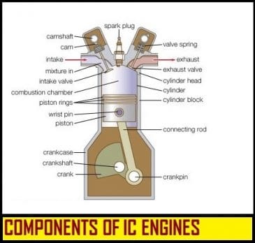
Note that the connecting rod is connected to the crankshaft offset from the center of the crankshaft. This means that as the piston moves up or down, it will cause the crankshaft to rotate. This is how a piston moving up or down can rotate the crankshaft which in turn spins the propellor.
The OTTO Cycle
Aircraft engines use a 4 stroke Otto cycle. That means the piston in a cylinder goes either up or down 4 times every time a spark plug fires and generates power. The crankshaft to which the piston is connected rotates 180 degrees every time the piston moves fully up or fully down (a stroke). The diagram below shows each of the 4 strokes associated with this movement.

The 4 strokes are:
- INTAKE stroke with only the intake valve open allowing fuel and air to be drawn into the cylinder.
- COMPRESSION stroke that compresses the fuel/air mixture. Note that both valves are closed.
- POWER stroke where the fuel/air mixture is ignited by the spark plug. NOte that both valves are closed.
- EXHAUST stroke where only the exhaust valve opens and the gases generated by the burned fuel/air mixture are pushed out of the cylinder
Piston / Crankshaft Terminology
When discussing cylinder movements, we use the rotated position of the crankshaft to describe where the piston is in the cylinder (the crankshaft rotates 3600). For example, when piston is highest in the cylinder, the crankshaft is said to be a 3600 (or 00) or TOP DEAD CENTER (TDC). When he piston is at its lowest point in the cylinder and the crankshaft is said to be at 1800 or BOTTOM DEAD CENTER (BDC). We can thereby describe where the piston its movement up or down by reference to these two points. For example, a piston moving up where the crankshaft angle is 3360 would be said to be 240 BEFORE TOP DEAD CENTER (BTC).
It is important that you understand these concepts if you are to understand how the SDSEFI system works.
Referring to the diagrams above, you will notice that certain things happen depending on where the piston is in the cylinder. For example, the intake and exhaust valve opening and closing is controlled by the camshaft which is mechanically linked to the crankshaft.
Control of when the spark plug fires is extremely important. The SDS ECU fires each cylinder’s spark plugs in a specific sequence based on where each cylinder’s piston is in the OTTO cycle. (For clarity, each aircraft cylinder typically has two park plugs which are fired at the same time.)
The SDS system uses magnets embedded in the flywheel and a HALL sensor located behind the flywheel to determine the crankshaft position. The magnets are installed in the precise locations in SDS supplied flywheels. The ECU knows the position of these magnets relative to TDC which means the ECU can determine when to fire the spark plugs in each engine cylinder.
Engine Timing
One often hears about “timing” or “setting the timing” of an engine. This refers to offsetting the spark event in the engine so that the spark occurs just before TDC is reached. When the fuel/air mixture is ignited by the spark, it does not all burn instantaneously. It therefore takes a small amount of time for the burn to occur all the while the crankshaft is turning. Typically we will ignite the fuel in an IO-540 engine 20-240 BTC. By the time the piston is in the downstroke after TDC, the maximum amount of pressure will be generated in the cylinder thereby maximizing the amount of work generated. This timing value is also set in the ECU. Unlike aircraft engines that use magnetos (which have a single timing value), the SDS ECU allows the timing value to vary with engine RPM. This can allow more time for the fuel to burn at low RPMs.
Lean of Peak (LOP)
When running Lean of Peak (LOP), the fuel/air mixture is leaner and thus burns more slowly. When running LOP, the SDS system allows an additional spark advance to be programmed. Advancing the spark when LOP allows more energy to be extracted (there is more time for fuel to burn) from the leaner mixture thereby partially offsetting the power lost when running a leaner mixture.
CAVEATS
Care must be taken to ensure that the spark advance is not too great. If the spark ignites too soon, it will put downward pressure on the piston as it is trying to rise in the cylinder. This can be quite destructive. Initially you should set the spark advance to no more than the engine manufacture’s recommendation.